
RLC参数测量仪的设计
无需注册登录,支付后按照提示操作即可获取该资料.
RLC参数测量仪的设计(论文10400字)
摘 要
本文对RLC参数测量仪的意义、发展趋势,主要技术原理进行了介绍。RLC参数测量仪是通过外围电路对RLC的参数进行测量,然后将信号传送给单片机。其原理是将RLC转换成频率,电阻电容是通过RC振荡电路转化的,电感是通过电容三点式振荡电路转化的,然后利用计数器测频后通过单片机做运算,被测元件类型可以通过按键选择,最后计算出待测元件的参数并在1602液晶屏幕上显示出来。RLC参数测量仪具有具有方便,准确,操作简单,体积小,易于携带等优点。它的设计制作运用了模拟电路,数字电路,及相关的单片机知识。
关键词:单片机 电阻测量 电容测量 电感测量
The design of the RLC parameter measurement instrument
ABSTRACT
In this paper, the significance and development trend of the RLC parameter measuring instrument are introduced, and the main technical principles are introduced. RLC parameter measuring instrument is to measure the parameters of RLC through the peripheral circuit, and then send the signal to the scm. Its principle is will measure the resistance and capacitance value, the electric inductance values change is transformed into the frequency, resistance and capacitance is transformed by RC oscillatory circuit inductor is transformed by three point capacitance circuit, then the counter frequency measurement by single chip microcomputer to do operation, measured element type can through the button selection, finally calculate the unmeasured component parameters and displayed in the 1602 LCD screen. RLC parameter measuring instrument has the advantages of convenient, accurate, simple operation, small size, easy to carry, and so on. It is designed to make use of analog circuits, digital circuits, and related SCM knowledge.
Key words:STC89C52 single chip; resistor measuring; capacitance measuring ;inductance measurement


目 录
RLC参数测量仪的设计 I
摘 要 I
The design of the RLC parameter measurement instrument II
ABSTRACT II
第一章 绪论 1
1.1研究背景和目的 1
1.2发展现状和趋势 1
1.3主要原理和技术 2
1.4设计任务 2
第二章 设计方案的比较 3
2.1RLC参数测试仪设计方案的比较 3
2.2 测量RLC单元电路的方案比较 4
2.2.1电阻测量方案 4
2.2.2电容测量方案 5
2.2.3电感测量方案 7
第三章 设计思路和单元电路的设计 9
3.1设计思路 9
3.2单元电路的设计 9
3.2.1测Rx电路设计 9
3.2.2测Cx电路设计 10
3.2.3测Lx电路设计 11
3.2.4控制电路的设计 12
3.2.5显示电路的设计 13
3.2.6按键电路的设计 15
3.2.7报警电路的设计 15
第四章 软件设计和仿真调试 16
4.1主程序设计 16
4.2 R键功能设计 17
4.3报警子程序设计 18
4.4电路仿真 19
4.4.1测量电阻时局部电路仿真输出波形 19
4.4.2测量电容时局部电路仿真输出波形: 20
4.4.3测量电感时局部电路仿真输出波形: 20
4.5测量电阻的仿真 20
4.6测量电容的仿真 21
4.7 测量电感的仿真 22
4.8仿真数据 23
4.9硬件调试 24
4.9.1测量电阻 24
4.9.2测量电容 25
4.9.3测量电感 25
4.9.4数据采集 26
4.10总结 27
参考文献 29
致谢 31
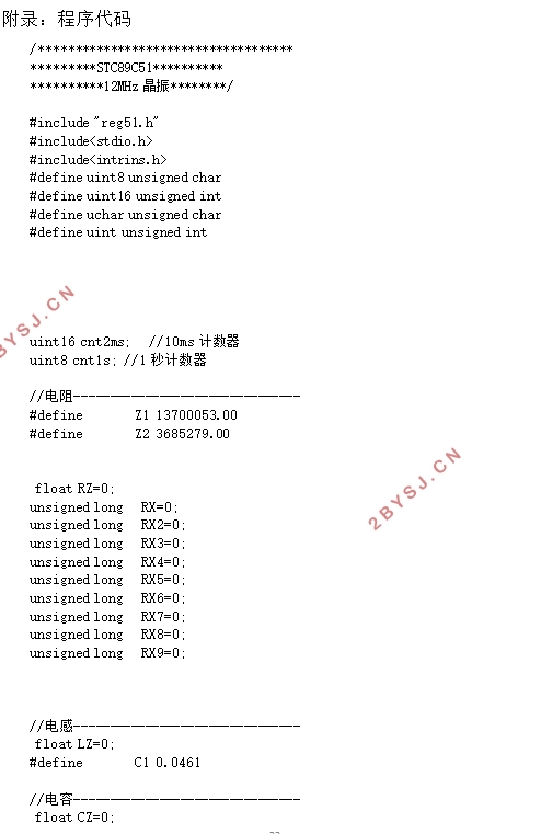
附录 :程序代码 32