基于PLC三自由度机械手控制系统的设计(10kg负载)(含CAD零件图装配图)
无需注册登录,支付后按照提示操作即可获取该资料.
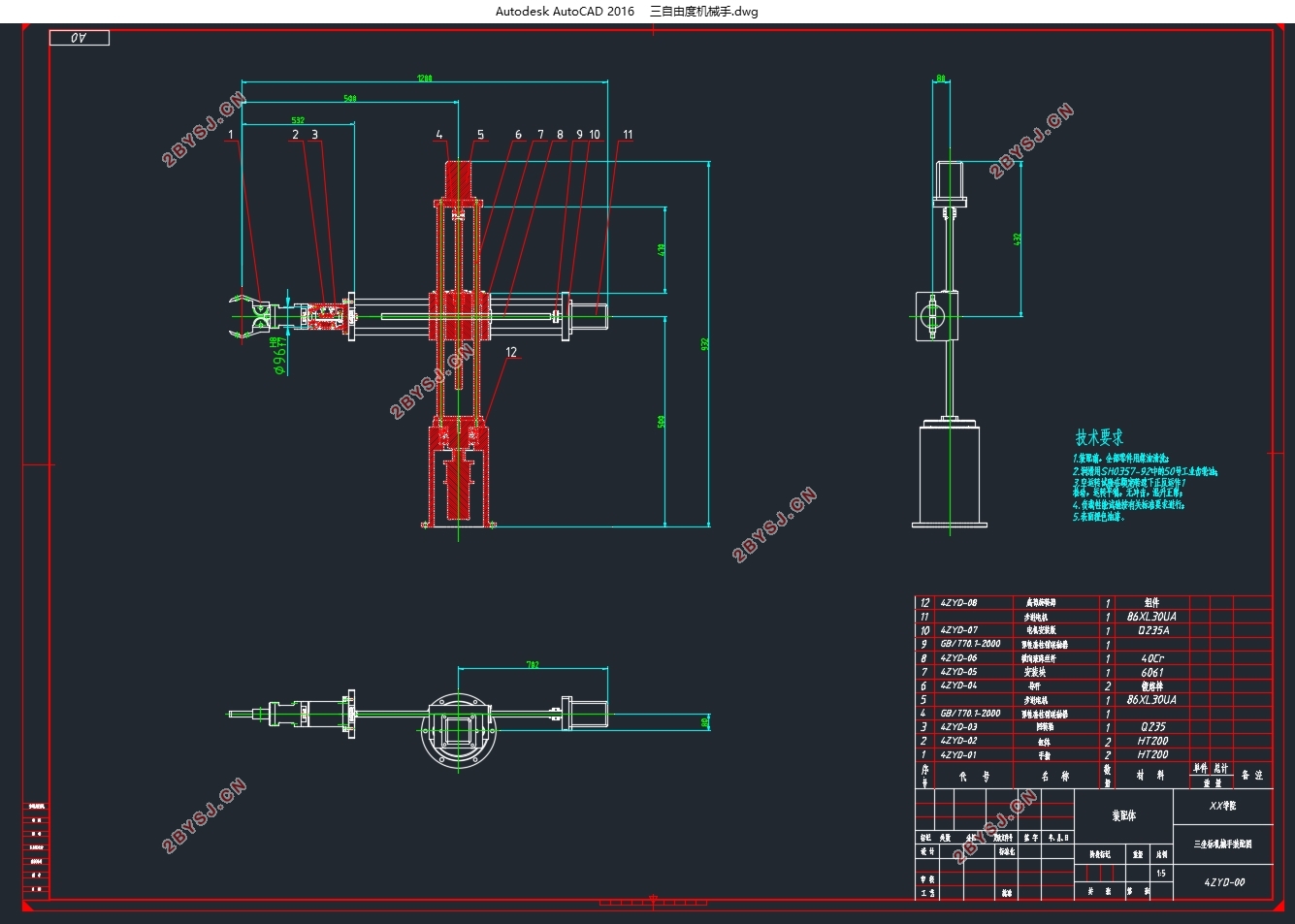
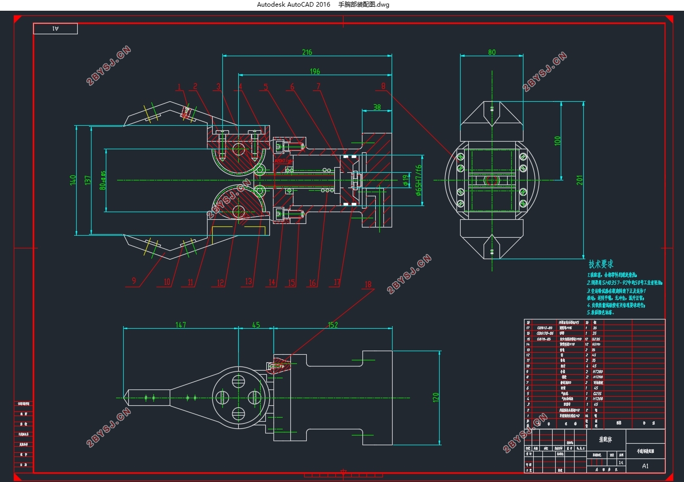
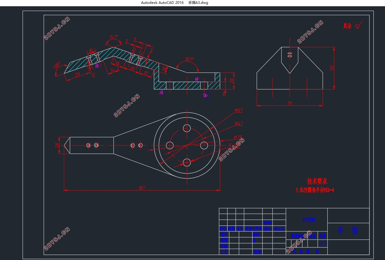
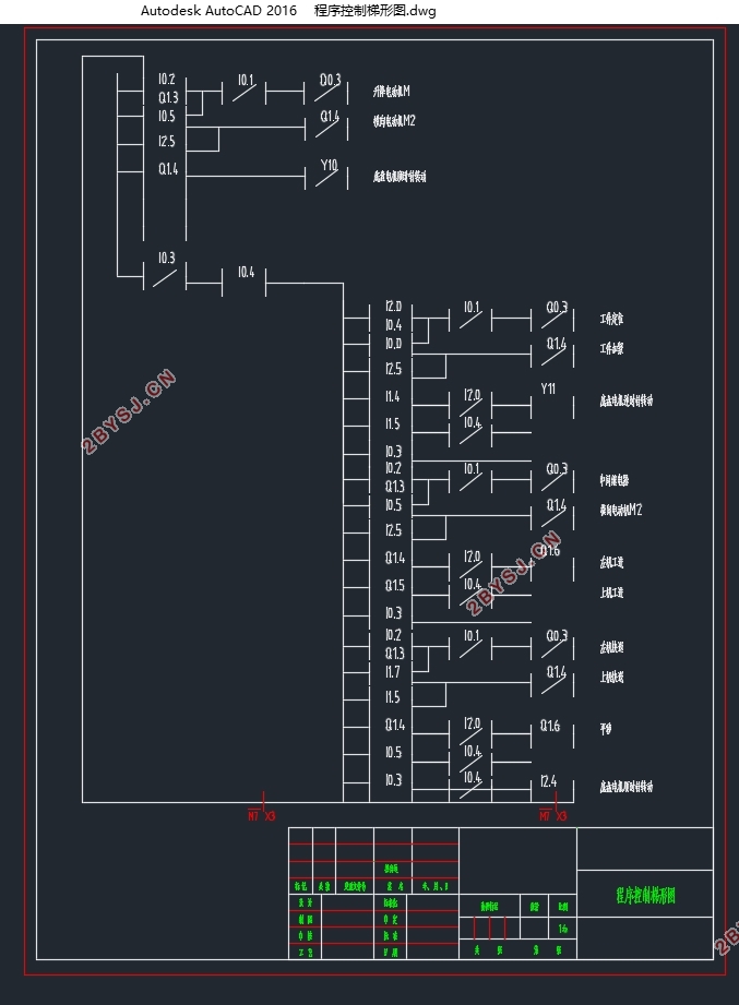
基于PLC三自由度机械手控制系统的设计(10kg负载)(含CAD零件图装配图)(任务书,开题报告,论文说明书15000字,CAD图7张)
摘要
本文首先简要介绍了工业机器人的工业机器人和工业机器人的概念,工业机器人的分类和组件。它的自由度和坐标控制,机器人气缸技术的特点,PLC控制机器人的特点,以及国内外工业机器人发展的现状。
本文首先根据负载要求设计机械手使用手持结构,并确定机器人控制坐标形式和技术参数。然后,设计操纵器的手腕的摆动部分的结构,并计算和检查手腕旋转所需的驱动扭矩和由旋转圆筒提供的驱动扭矩。
根据机械手的工作要求,设计了与机械手配套的气动系统,绘制出气动系统的工作原理图。
选择PLC控制机械手,选择合适的PLC模型,根据工作流程设计PLC控制方案,绘制工业机器人时序图,绘制PLC控制程序图。
关键词:工业机器人机械手腕气动可编程控制器(PLC)
ABSTRACT
Firstly, this paper briefly introduces the concept of industrial robots and industrial manipulators, the classification and components of industrial robots, their degrees of freedom and coordinate control forms, the characteristics of cylinder technology for manipulators, the characteristics of PLC control manipulators, and the development status of industrial robots at home and abroad.
Firstly, according to the load requirement, this paper preliminarily designs the structure of the manipulator using the holding hand, and determines the control coordinate form and technical parameters of the manipulator. Then the structure of the rotating part of the wrist of the manipulator is designed, and the driving moment needed when the wrist rotates and the driving moment provided by the rotary cylinder are calculated and checked.
According to the working requirements of the manipulator, the pneumatic system supporting the manipulator is designed, and the working principle diagram of the pneumatic system is drawn.
Select the PLC control manipulator, select the appropriate type of PLC, and compile the PLC control scheme according to the workflow design, draw the industrial manipulator working state sequence diagram, draw the PLC control program diagram.
Key words: Industrial Robot; Mechanical Wrist;Pneumatic;Programmable Logic Controller (PLC)
机械手的主要参数
1.机械手的负载是设计时的主要参数,本设计的设计要求负载为10kg。
2.移动速度是机器手的基本参数。操作频率要求了机械手的运动速度,如果速度过低会限制其的应用范围。机械手主要的速度参数是机械手的伸缩速度以及回转速度。
该机械手最大移动速度设计为10m/s。最大回转速度设计为90°/s。平均移动速度为0.8m/s。平均回转速度为60°/s。机械手动作时有启动、停止过程的加、减速度存在,用速度一行程曲线来说明速度特性较为全面,因为平均速度与行程有关,故用平均速度表示速度的快慢更为符合速度特性。定位精度也是基本参数之一。该机械手的定位精度为±1mm.


目录
第一章 绪 论 1
1.1工业机械手概述 1
1.2 机械手的组成和分类 1
1.2.1机械手的组成 1
1.2.2 机械手的分类 3
1.3 国内外发展情况 5
1.4课题的提出及主要任务 6
1.4.1课题的提出 6
1.4.2工业机器人主要技术性能参数 7
1.4.3课题的主要任务 8
第二章 机械手的设计方案 9
2.1机械手的座标型式与自由度 9
2.2机械手的手腕结构方案设计 10
2.3机械手的驱动方案设计 10
2.4 机械手的手臂结构方案设计 10
2. 5 机械手的驱动方案设计 11
2. 6 机械手的控制方案设计 11
2. 7 机械手的主要参数 11
2.8 机械手的技术参数列表 11
第三章 手部结构设计 14
3.1 夹持式手部结构 14
3.1.1手指的形状和分类 14
3.1.2设计时需要考虑的问题 14
3.1.3 手部夹紧气缸的设计 15
第四章 手腕结构设计 20
4.1 手腕的自由度 20
4.2手腕的驱动力矩的计算 20
4.2.1 手腕转动时所需的驱动力矩 20
4.2.2 回转气缸的驱动力矩计算 23
4.2.3 手腕回转缸的尺寸及其校核 24
第五章 手臂气缸的尺寸设计及校核 28
5.1 手臂伸缩气缸的设计及校核 28
5.1.1 手臂伸缩气缸的尺寸设计 28
5.1.2 尺寸校核 28
5.1.3.导向装置 29
5.1.4 平衡装置 29
5.2 手臂的升降气缸的尺寸设计 29
5.2.1 尺寸设计 29
5.2.2 尺寸校核 29
5.3 手臂回转气缸的尺寸设计 30
5.3.1 尺寸设计 30
5.3.2 尺寸校核 31
第六章 气动系统设计 33
第七章 机械手的PLC控制设计 35
7.1 可编程序控制器的选择及工作过程 35
7.1.1 可编程控制区的选择 35
7.1.2 可编程控制区的工作过程 35
7.2 可编程控制器的使用过程 36
7.3 机械手可编程控制器控制方案 37
7.3.1 系统简介 37
7.3.2 机械手的工作流程 37
7.3.3 机械手工作时序图如附图所示 38
7.4 机械手控制程序 38
第八章 成本估计 43
第九章 结论 44
参考文献 45
致谢 46
