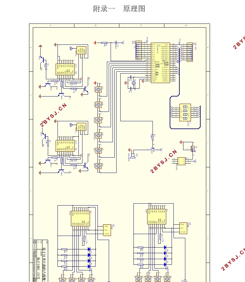
基于51单片机的八路数字抢答器设计
无需注册登录,支付后按照提示操作即可获取该资料.
基于51单片机的八路数字抢答器设计(任务书,开题报告,论文11000字)
摘要
抢答器是一种为方便抢答者进行抢答而设计的裁判器,常用于各种娱乐竞赛活动、知识竞答等场合。本论文介绍的是一种利用单片机作为核心元件、无线信号作为抢答信号的八路抢答器,通过程序设置抢答时间与答题时间,按键实现系统控制与复位,并且能够通过无线收发模块实现无线抢答功能。
本设计采用STC89C51单片机实现抢答控制功能,采用315M无线收发模块实现无线信号的抢答,主要包括以下部分:单片机最小系统、控制电路模块、抢答模块、无线收发模块、报警电路模块、显示模块等,整个系统布局简单,结构合理,能够全部实现普通抢答器的功能。
关键词:多路数字抢答器 单片机 无线收发
The design of the eight digital Responder based on 51 MCU
Abstract
Responder is a priority judgment circuit designed for contestants when answering a quiz, widely used in all kinds of entertainment contest,knowledge match and other occasions.This paper describes eight-way Responder which usesMCU as a core component and wireless signal as answer signal.This Responder can set the time and answer time, achieve clearing and controlling systems, and can answer functionality through wireless radio transceiver module.
This design uses STC89C51 MCU for answering function, and 315M wireless transceiver module for wireless signals answer, Including the smallest single-chip system, the control circuit modules, wireless transceiver modules, alarm circuit module, display circuit module.The layout of the entire system is simple and reasonable. It can achieve full functionality of ordinary Responder.
Key Words:Multi-channel digital Responder; MCU; Wireless transceiver


目录
摘要 I
Abstract II
第一章 绪论 1
1.1 多路数字抢答器的应用背景 1
1.2 多路数字抢答器的研究现状和技术应用 1
1.3 多路数字抢答器的设计意义 2
第二章 方案的设计与选择论证 3
2.1 方案设计任务和要求 3
2.1.1 基本任务与要求 3
2.1.2 扩展内容 3
2.2 设计方案及其论证 3
2.2.1 单片机型号选择 3
2.2.2 供电电源模块 4
2.2.3 显示电路模块方案 4
2.2.4 报警模块方案 4
2.2.5 无线收发模块方案 5
2.2.6 系统最终方案 5
第三章 八路数字抢答器的硬件电路设计 7
3.1 系统整体介绍 7
3.2 单片机最小系统 8
3.3 抢答器的原理 9
3.4 功能模块电路 10
3.4.1 供电电路 10
3.4.2控制电路模块 10
3.4.3 选手抢答键 11
3.4.4 显示电路模块 11
3.4.5报警电路模块 12
3.4.6 无线发射电路 13
3.4.7 无线接收电路 15
第四章 八路数字抢答器的软件设计 19
4.1程序流程 19
4.1.1 程序流程概述 19
4.1.2 抢答成功流程 21
4.2 无线收发模块软件介绍 22
4.2.1 SC2262编码介绍 22
4.2.2 编码流程 24
4.2.3 解码流程 24
第五章 系统的调试分析 26
5.1 硬件焊接 26
5.2 硬件调试 26
5.2.1 抢答计时 26
5.2.2 显示抢答成功 27
5.2.3 答题计时 28
5.2.4 时间调整 28
5.3 硬件调试问题及解决方法 29
5.4 软件调试 30
第六章 总结与展望 31
6.1 总结 31
6.2 展望 31
参考文献 32
致谢 33
附录一 原理图 34
附录二 实物图 35
附录三 程序清单 36
