基于摄像头的智能车系统设计(单驱动寻白线)(CAD,程序,电路图)
无需注册登录,支付后按照提示操作即可获取该资料.
基于摄像头的智能车系统设计(单驱动寻白线)(CAD,程序,电路图)(任务书,开题报告,毕业论文16800字,cad图5张,电路图,录像,答辩PPT)
摘要
该智能车控制系统采用MC9S12XS128 的16位单片机作为的核心控制单元, 通过CCD模拟摄像头采集道路图像,将处理的信号输入核心控制单元,控制单驱动的模型小车沿着白底黑线的跑道自动寻迹。在控制策略上,根据采集到的数据分析行驶路径以及对起跑线进行检测,采用PID 算法对赛车的直流电机进行闭环控制,并判断跑道的弯曲程度采用PD的转向控制策略。在机械结构方面,通过对模型小车参数的优化,和对舵机输出力臂的改造,进一步提高了赛车的性能。
智能车的控制系统需要硬件、软件以及机械等方面相互协调,更需要借助一些调试工具才能不断的调整与完善。
关键字:CCD摄像头;智能车;自动寻迹;MC9S12XS
Design of Intelligent vehicle Car Based on camera (Single drive to find white line)
Abstract
The intelligent vehicle control system adopts MC9S12XS128 16 bit single chip microcomputer as the core control unit, is simulated by CCD camera capture images of the road, will deal with the signal input core control unit, to control the single driving model car along the white line track automatic tracing.In the control strategy, according to the collected data analysis route and on the starting line detection, using PID algorithm on the car for DC motor closed-loop control, and determine the degree of bending of the runway by PD steering control strategy.In the mechanical structure, based on the parameter optimization model car, and the actuator output lever arm of the transformation, to further improve the performance of the car.
Intelligent vehicle control system hardware, software and mechanical aspects of coordination, more needs some debugging tool can continuously adjust and perfect.
Keywords: CCD camera; Smart Car; Auto Tracing; MC9S12XS
1 机械结构设计与实现
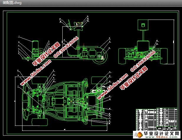
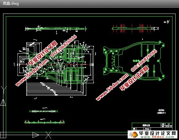
机械结构设计主要包括对模型前后轮的调校、车体底盘重心的调整、舵机的安装、CCD传感器的安装和速度编码器的安装等。
2 单片机
飞思卡尔公司的MC9S12XS128芯片
3 智能车系统硬件设计与实现
智能车系统所需的硬件涉及摄像头的选型及相关参数说明工作原理等、电路总体分布、电源管理模块、驱动电路、拨码开关、LM1881视频分离模块、串行通讯接口电路。
4 智能车系统软件设计
智能车系统软件设计包括系统模块介绍及系统初始化、摄像头的、黑线提取、CCD摄像头的路径识别、起始线的判别、舵机PD控制策略、速度PID控制策略、起跑线的检测。


目 录
第一章 绪论 1
1.1智能车的发展 1
1.2智能车应用前景和意义 1
第二章 机械安装 3
2.1 智能车总体构造 3
2.1.1 车模底盘调整 3
2.1.2 前轮的调整 3
2.1.3 后轮的调整 4
2.2其它的安装 5
2.2.1 舵机的安装 5
2.2.2 测速传感器的安装 5
2.2.3 摄像头的安装 6
第三章 智能车硬件电路设计 7
3.1 主控芯片MC9S12XS128 7
3.1.1 MC9S12XS128芯片介绍 7
3.1.2 最小系统 7
3.2 摄像头传感器 9
3.2.1 摄像头传感器的选择 9
3.2.2 传感器的工作方式 9
3.3 电源模块 11
3.4其余的电路 13
3.4.1 直流驱动电机控制 13
3.4.2 舵机控制单元 13
3.4.3 拨码开关电路 14
3.4.4 LM1881视频分离模块 14
3.4.5 车速检测模块 15
3.4.6 串口调试模块 16
3.4.7 二值化转换模块 16
第四章 软件设计和实现 17
4.1软件系统主流程 17
4.2系统的初始化 18
4.2.1 时钟模块 18
4.2.2 PWM输出模块 19
4.2.3 A/D转换模块 20
4.2.4 定时模块 20
4.2.5 串口初始化 21
4.3 图像采集和黑线提取算法设计 21
4.3.1 图像采集 21
4.3.2 黑线提取 23
4.4 舵机的控制 23
4.4.1弯道的判断 23
4.4.2 PD策略 24
4.5 电机转动控制 25
4.5.1 PID控制算法 25
4.5.2 速度控制策略 26
4.6 起跑线的检测 26
第五章 系统调试 28
5.1 开发环境的使用 28
5.2 BDM调试器的使用 32
5.2.1 Hiwave初始参数设置 32
5.2.2 程序下载 33
5.2.3 程序调试 34
第六章 智能车技术参数说明 35
参考文献 36
致谢 37
附录A 38
附录B 55
