单向三车道襄樊市珍珠泉大桥施工图设计(含CAD图)
无需注册登录,支付后按照提示操作即可获取该资料.
单向三车道襄樊市珍珠泉大桥施工图设计(含CAD图)(任务书,开题报告,外文翻译,论文计算书30000字,CAD图纸18张)
摘要
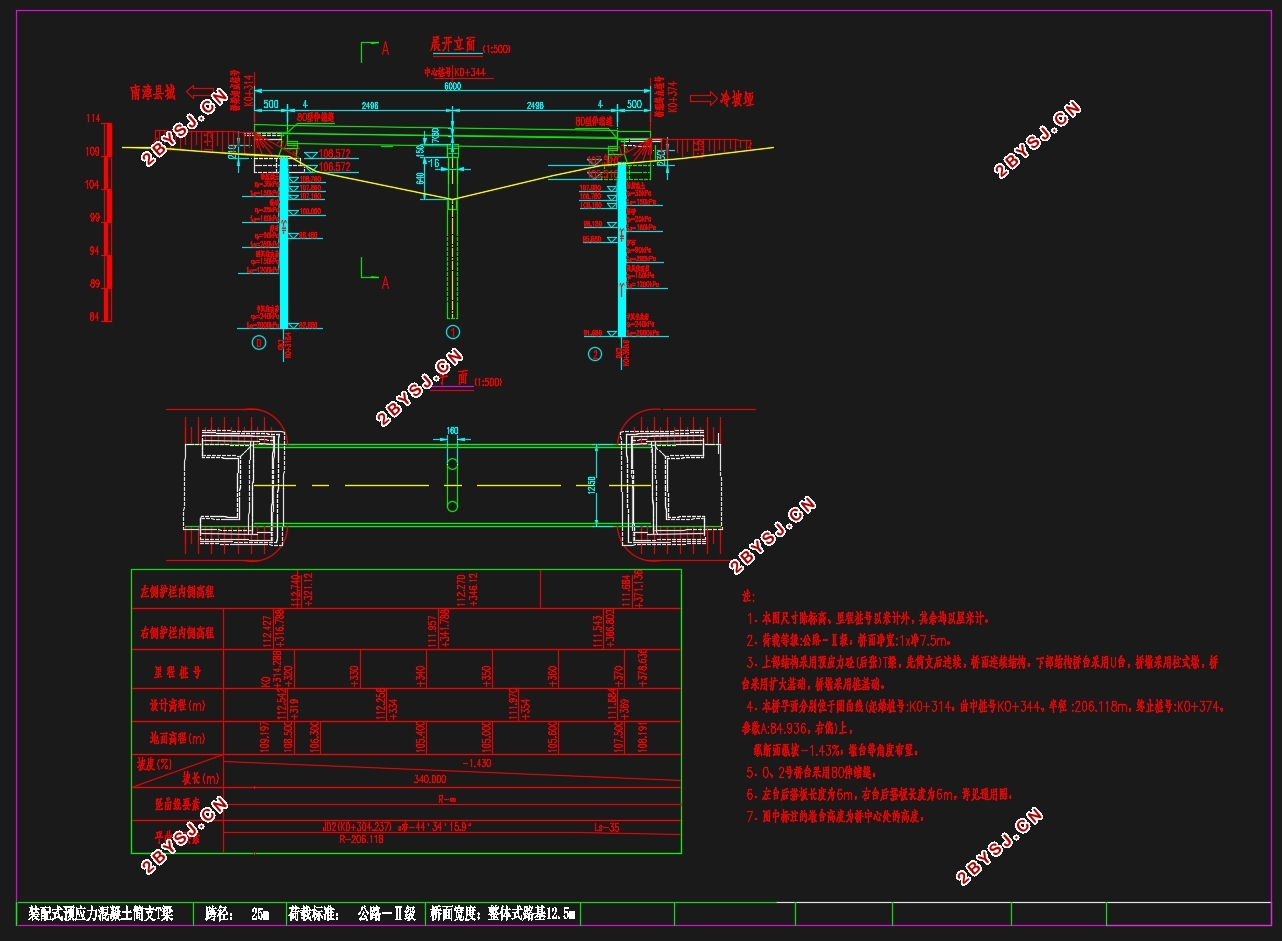
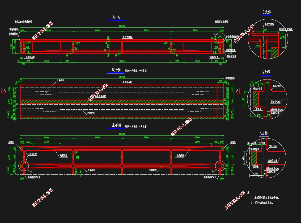
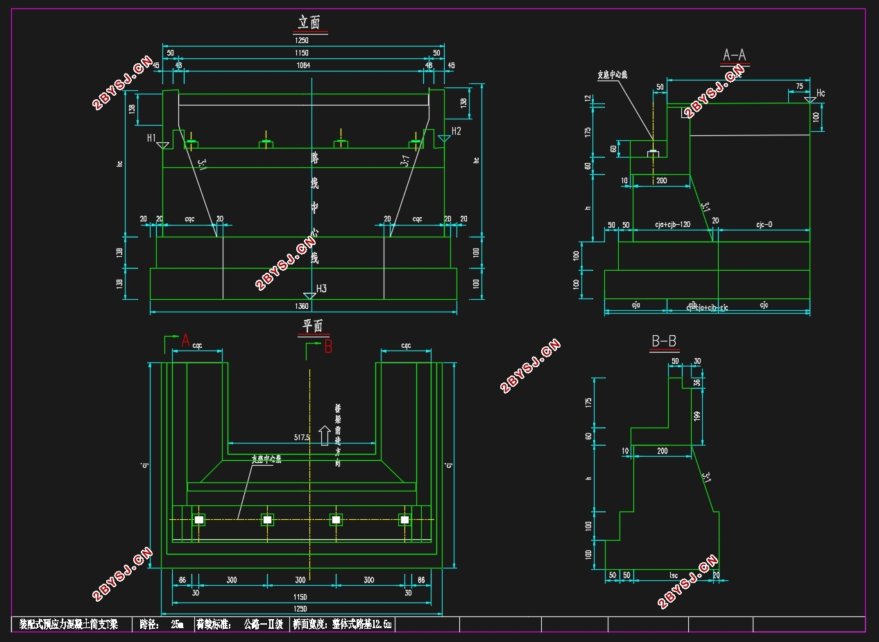
本次毕业设计的题目为襄樊市南冷路珍珠泉大桥施工图设计。是建立在实际工程上的一个毕业设计。在设计中选用25m跨径的预应力T梁,结构形式采用结构简直桥面连续结构,跨数设置为2跨。本次设计梁宽为12.5m,设计为3.75mx3的行车道板外加0.5mx2的护栏,剩余的0.25m对称分布在道路左右两侧。本次施工图设计的主要任务上部结构和下部结构两个大方向的计算。而本次设计应要求采用手算加电算相结合的方式。在上部结构采用有限元法midas计算软件进行计算,下部结构采用手算。主要计算内容有截面尺寸的拟定,midas的建模,用midas进行内力计算和配筋计算。下部结构计算盖梁,桥墩和钻孔灌注桩的尺寸拟,内力计算和配筋设计。
关键词:预应力混凝土T梁桥;结构简直桥面连续;内力验算;配筋等
Abstract
The title of this graduation project is the construction design of the Pearl Spring Bridge in Nanliang Road, Xiangfan City. It is a graduation project based on actual engineering. In the design, a 25m-span prestressed T-beam is selected. The structural form adopts the simple structure of the bridge deck and the span is set to 2 spans. The beam width of this design is 12.5m. The 3.75mx3 roadway is designed with a 0.5mx2 guardrail. The remaining 0.25m is symmetrically distributed on the left and right sides of the road. The main tasks of this construction drawing design are the calculation of the two major directions of the upper structure and the lower structure. This design should require the use of a combination of hand calculations and calculations. The upper structure is calculated using the finite element method midas calculation software, and the lower structure is calculated by hand. The main calculations include the formulation of section dimensions, midas modeling, and midas for internal force calculations and reinforcement calculations. The lower structure is used to calculate the dimensions of the girder, piers and cast-in-place bored piles, calculation of internal forces and reinforcement design.
Key words:Prestressed concrete T-beam bridge; structure simple bridge continuous; internal force checking; reinforcement, etc.


设计标准
荷载选取:公路II级荷载。
桥面铺装设置:桥面宽度为12.5m宽,净宽11.5m,在两侧设置各0.5m的防撞层,车道采用单向三车道。剩余0.25m对称分布在车道两侧。
桥跨设置:桥跨数目设置为2跨,跨径设置为每跨25m,总长50m
目录
目录 V
1绪论 1
1.1 概述 1
1.2 本设计的意义 1
2 设计基本资料 3
2.1 设计标准 3
2.2 设计资料 3
2.3设计内容 3
2.4 技术标准与设计规范 3
3 预应力混凝土T梁内力计算 4
3.1 初拟结构尺寸 4
3.1.1 横断面初布 4
3.1.2 主梁结构尺寸初拟 4
3.2 截面几何特性 6
3. 3横隔梁的设置 10
4 Midas/civil建模及主梁内力计算 10
4. 建模过程 11
4.1 设定建模操作环境 11
4.2 定义材料 12
4.3 节点单元建模方法 13
4.4 节点单元截面信息 14
4.5 定义时间依材料特性 18
4.6 定义边界条件及边界组 20
4.7 建立静力荷载工况 20
4.8 移动荷载工况的定义 24
4.9 生成结果内力图 27
5预应力钢束布置 32
5.1钢束数量 32
5.2预应力损失计算 36
6.1结构验算 44
6.1截面极限承载能力验算 44
6.1使用阶段截面抗裂验算 61
6.1持久状况构件的应力验算 75
6.1短暂状况构件的应力验算 84
第7章下部结构设计 88
7.1设计资料 88
7.2 盖梁 89
7.2.1荷载计算 89
7.2.2盖梁配筋计算 97
7.3 桥墩墩柱 98
7.3.1荷载计算 98
7.3.2 截面配筋计算 99
7.4 钻孔灌注桩计算 100
7.4.1 设计资料 100
7.4.2荷载计算 101
7.4.3 桩长计算 101
7.4.4桩的内力计算 102
7.4.5 桩顶纵向水平位移验算 104
7.4.6 桩截面配筋计算 105
参考文献 107
