
马鞍山某污水处理厂25万吨污水处理工程设计(含CAD图)
无需注册登录,支付后按照提示操作即可获取该资料.
马鞍山某污水处理厂25万吨污水处理工程设计(含CAD图)(任务书,开题报告,外文翻译,计算说明书9000字,CAD图15张)
摘要
本次毕业设计的题目为马鞍山某污水处理厂工艺设计。主要任务是进行该污水厂二期工程所有工艺施工图设计。
马鞍山污水处理厂的建设规模:250000m3/d;原水水质:CODCr: 430mg/L, BOD5: 270mg/L;SS: 210mg/L;NH3-N: 35mg/L;TP:2.7mg/L;pH:6-9。要求处理后水质达到国家《城镇污水处理厂污染物排放标准》(GB18918-2002)一级 A 标准的要求:CODCr≤50mg/L,BOD5 ≤10mg/L,SS≤10mg/L,NH3-N≤5mg/L,TP≤0.5mg/L。
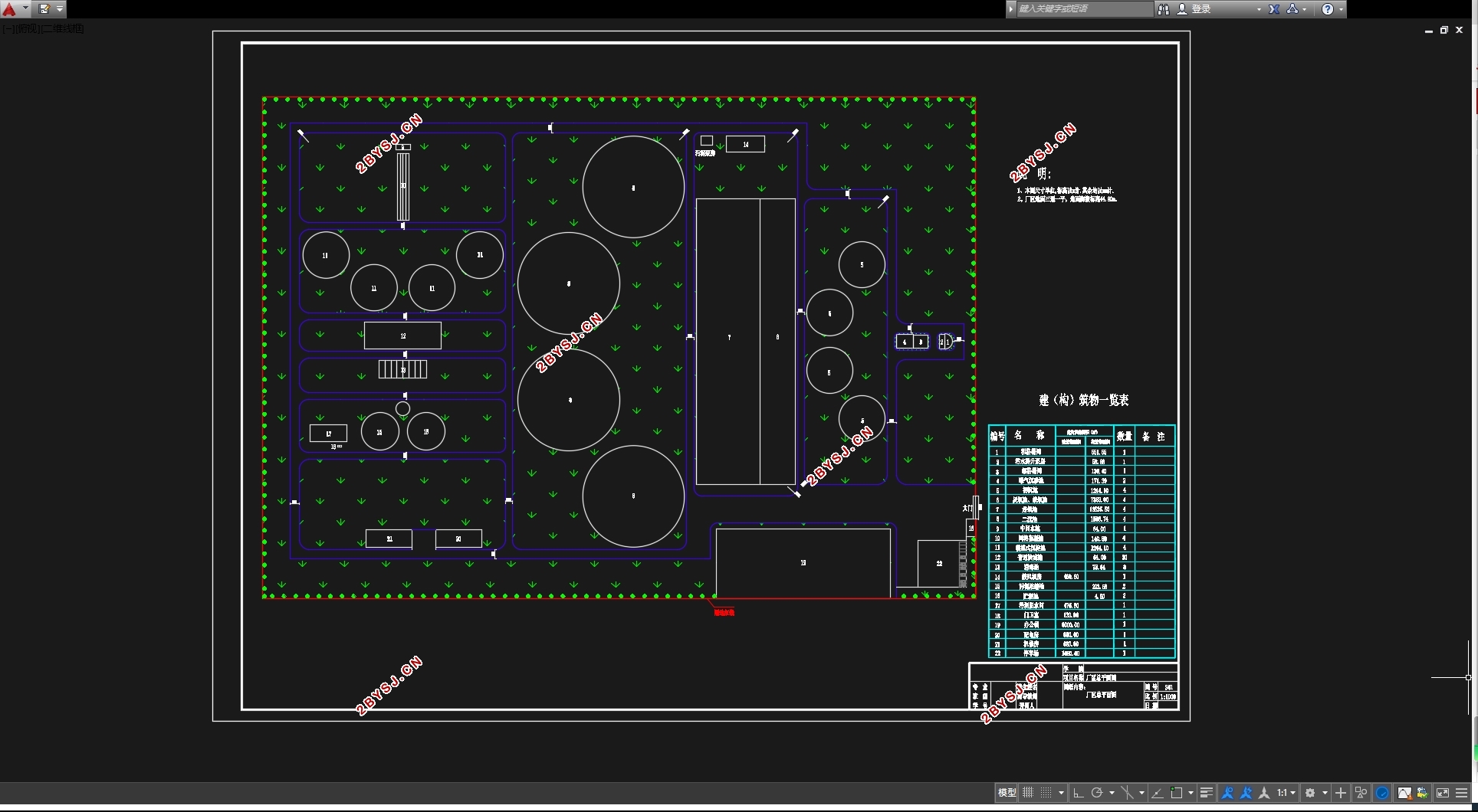
根据其进水水质、水量及出水情况,分析比较了各种污水处理工艺,确定该污水处理厂采用传统的A2O工艺。由于传统A2O工艺达不到一级A标准,所以对二沉池出水要进行深度处理(混凝、沉淀、过滤、消毒)。处理构筑物主要有曝气沉砂池,好氧池,二沉池等,产生的污泥经污泥浓缩池、脱水间脱水后外运。
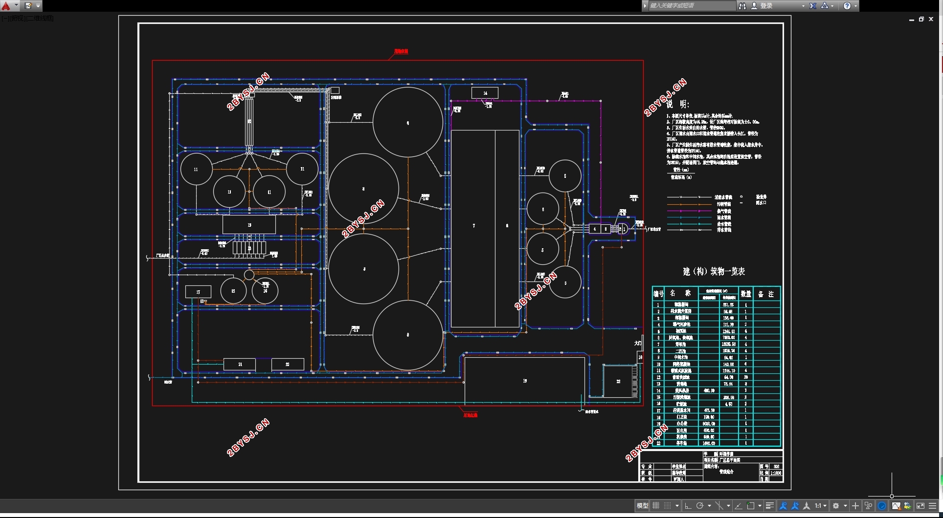
主要设计内容包括:污水处理工艺选择及各工艺单元的设计(包括工艺流程的确定及各单体构筑物的设计);污泥处理工艺设计,(包括工艺流程的确定及各单体构筑物的设计);污水处理厂的平面及高程布置(包括污水处理厂处理构筑物和辅助构筑物的平面图及高程图的绘制)。
关键词:污水处理,A2O工艺,构筑物,工程,设计
Abstract
The graduation design topic for the ma’anshan yanghegeng sewage treatment plant process design. The main task is to complete all the sewage processing design of the second phase of the sewage treatment plant.
Ma’anshan yanghegeng sewage treatment plant the construction scale: 250000m3/d ,The original water:
CODCr : 430mg/L, BOD5: 270mg/L;SS: 210mg/L;NH3-N: 35mg/L;TP:2.7mg/L;pH:6-9 for handling the water quality to achieve after the country ”the urban sewage treatment plant emissions standards(GB18918-2002)”level 1A standard requirements: CODCr than 50 mg/L ,more than 10mg/L,more than 10mg/L BOD5, SS than 10mg/L, NH3-N than 5mg/L, TP than 0.5mg/L.
According to the water quality, water yield and the effluent condition, Analysis and comparison of various wastewater treatment process, the sewage treatment plant adopt the conventional A2O process. Since the conventional A2O process could not achieve level 1A standard ,we must conduct depth of the processing(Coagulation ,Precipitation ,Filtration ). The treatment structures consist of Aerated grit chamber, Aerobic pond ,The Two sink pond etc.
The main design content includes: choosing the wastewater treatment process and the process of design unit (including process flow and the determination of the monomer structures design); The sludge treatment process design, (including process flow and the determination of the monomer structures design); Sewage treatment plants the plane and elevation layout (including sewage treatment plant structures and auxiliary structures plan and elevation drawing).
Key words:wastewater treatment, A2O process, construct buildings, design, engineering.
1.1.1 设计目的
通过完成城镇污水处理工艺的设计,掌握工程设计的基本步骤,掌握城市污水处理工艺流程设计、厂区平面图布置以及各处理单元构筑物设计计算的基本方法。
1.1.2 设计要求
马鞍山拟再建一污水处理厂,收集城区生活污水,项目采取BOT模式。分两期建设,第一期处理规模为水量125000立方米/天,二期规模是250000立方米/天。根据相关政策,建设方一次性完成征地,市政府已经完成征地工作,如图中红线所示。厂区外污水管网由政府负责完成,污水进管内径为2米,管底埋深为-3.6米。
本次任务,要求进行该污水厂二期工程所有工艺施工图设计,出水要求达到污水综合排放标准一级A标准,处理出水排入长江,河流低水位,低于污水拟建厂区2.8米,高水位低于拟建厂区1.1米。厂区征地后三通一平,地面水平。海拔标高44.28米。
1.2、主要技术参数
1.2.1处理水量
污水量:Q = 250000 m3/d =1.04×10⁴m3/h=2893.52L/s
变化系数:KZ=1.22
最大日流量:Qmax=KZ*Q=1.22*2893.52=3530.1L/s

目录
摘要 ……………………………………………………………………1
ABSTRACT ………………………………………………………………2
1、 设计任务 ……………………………………………………………6
1.1、 主要内容及要求 ……………………………………………………6
1.1.1 设计目的 ……………………………………………………6
1.1.2 设计要求 ……………………………………………………6
1.2、 主要技术参数 ……………………………………………………6
1.2.1 处理水量 ……………………………………………………6
1.2.2 污水水质 ……………………………………………………6
2、 污水处理厂设计计算 …………………………………………………7
2.1、 污水处理工艺单元设计计算 …………………………………………7
2.1.1 粗格栅 ………………………………………………………7
2.1.2 进水泵房 ……………………………………………………9
2.1.3 细格栅 ……………………………………………………10
2.1.4 曝气沉砂池 …………………………………………………12
2.1.5 初沉池 ……………………………………………………13
2.1.6 生物反应池(A2O工艺) ………………………………………14
2.1.7 二沉池 ……………………………………………………21
2.2、深度处理工艺单元设计 ……………………………………………23
2.2.1 中间水池 ……………………………………………………23
2.2.2 网格絮凝池 …………………………………………………24
2.2.3 辐流式沉淀池 ……………………………………………24
2.2.4 普通快滤池 ………………………………………………25
2.2.5 紫外消毒 …………………………………………………31
2.3、污泥处理系统的设计计算 …………………………………………32
2.3.1 污泥浓缩池 ………………………………………………32
2.3.2 贮泥池 ……………………………………………………34
2.3.3 污泥脱水机房 ……………………………………………34
3 、污水处理厂的平面布置及高程布置 ……………………………………35
3.1、平面布置 …………………………………………………………35
3.1.1 平面布置的一般规则 ………………………………………35
3.1.2 主要构筑物和建筑物的尺寸 …………………………………35
3.2、高程布置 ……………………………………………………………36
3.2.1 布置原则 …………………………………………………36
3.2.2 各构筑物高程计算 …………………………………………36
致谢 …………………………………………………………………………………37