四跨(50+2×75+50)m预应力混凝土连续刚构桥设计(含CAD图)
无需注册登录,支付后按照提示操作即可获取该资料.
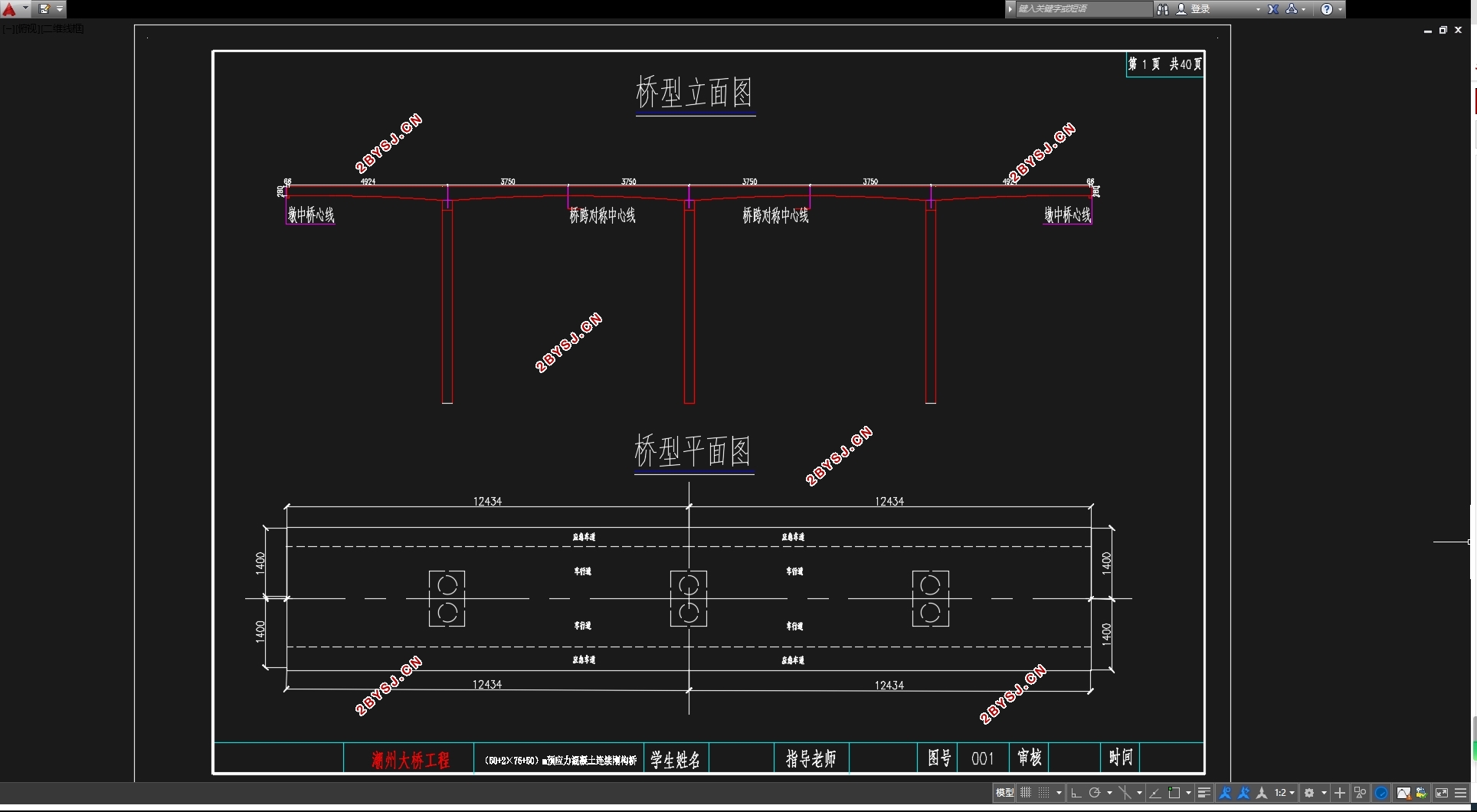
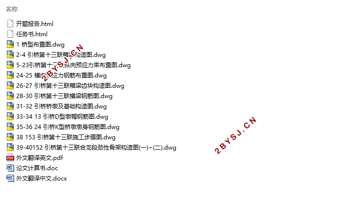
四跨(50+2×75+50)m预应力混凝土连续刚构桥设计(含CAD图)(任务书,开题报告,外文翻译,论文计算书20000字,CAD图11张)
摘要
预应力混凝土连续刚构桥近年来广泛应用到工程中,其结构存在着很多其他结构所不具备的优点,在工程选择上受到了很高的青睐。适合修建大跨径的桥梁,并且具有很多的天然优点,例如:防震效果好,后期养护方便,并且由于连续桥的桥墩和主梁相互固结,因次连续刚构桥的桥面车辆行驶会更加的平稳。在施工方面,连续刚构桥也具有T形刚构的优点。
本次内容为(50+2×75+50)m预应力混凝土连续刚构桥设计,单幅桥面宽度布置为:0.25m桥轴平面线形为直线。荷载等级为公路—I 级。梁断面为单箱单室截面。采用悬臂施工法。结构计算采用 Midas/civil 软件进行桥梁结构的设计和验算,主要包括:截面强度验算、截面应力验算、预应力混凝土抗裂验算等
此次设计技术方案主要包括利用MADAS建立连续箱梁桥的模型并且进行加载(加载包括恒载和活载),进行结构内力的分析并且通过采用悬臂施工法施工。
关键词:连续钢构桥 ; 预应力 ; 悬臂施工法 ; 有限元模型 ;结构分析 ; 结构设计
Abstract
The continuous rigid structure of prestressed concrete has been welcomed by many projects in recent years. Its structure has advantages that many other structures do not have. There was a lot of choice in engineering choices,It is suitable for the construction of large cross-diameter Bridges, and it has a lot of advantages. For example, shock effect is good,late maintenance is convenient. Because of the bridge pier and the main beam of the continuous bridge,cars will be more stable on the road. On the construction,the continuous rigid frame bridge also has the advantage of T-shaped rigid frame.
This design is (50 +2 × 75 +50) m prestressed concrete continuous rigid frame bridge design.The plane of the bridge is linear. Load rating of highway-I level. Beam cross section as a single box single room Cantilever construction method method of full support is adopted in this bridge construction. Structure calculation and analysis use Midas checking software to calculate. Including cross-section strength checking, cross-section stress checking, prestressed concrete crack test and so on.
The design of the program mainly includes the use of MADAS to establish a continuous box girder bridge model(Including dead load and live load). The internal force of the structure is analyzed and constructed by cantilever construction.
Keywords: Continuous rigid frame bridge ; prestressing force ; antilever construction- method ; finite element model ; Structural analysis ; Structural design
设计资料及基本数据
广东潮州大桥引桥为第十三联为预应力混凝土连续刚构桥,跨径布置为(50+2×75+50)m,四跨,由于跨度大,桥型对称,因此采用悬臂施工法。主梁为单箱单室预应力混凝土结构,单幅梁宽14m;设计汽车荷载:公路-Ⅰ级;设计基准期:100年。


目录
41摘要 I
Abstract II
第一章:概述 1
1.1毕业设计意义 1
1.2 桥梁设计的基本要求 1
1.2.1使用上的要求 1
1.2.2经济上的要求 2
1.2.3结构尺寸和构造上的要求 2
1.2.4施工上的要求 2
1.2.5美观上的要求 2
1.3预应力混凝土连续刚构桥概述 2
1.3.1 刚构桥概述 2
1.3.2 连续刚构桥发展趋势 3
1.3.3 工程介绍 3
1.3.4地形地貌 3
1.35地质条件 4
1.4 设计资料及基本数据 4
1.5悬臂施工方法介绍 4
1.5.1 施工特点 4
1.5.2 工艺流程 4
第二章 结构初步设计 6
2.1 设计概述 6
2.2桥型图 6
2.3截面形式及截面尺寸拟定 6
2.3.1梁高尺寸拟定 6
2.3.2 横截面尺寸拟定 7
2.3.3 横隔板 7
2.4变截面箱梁形式 8
2.5尺寸详图及横断面布置 8
2. 6 施工阶段的划分 9
第三章 桥梁有限元模型建立 11
3.1 Midas Civil单元划分 11
3.1.2 施工阶段设计 11
3.2 主梁内力计算 11
3.2.1 恒载内力计算 11
3.2.2 活载内力计算 19
3.2.3 主梁作用效果组合 24
第四章 预应力钢束的估算和布置 25
4.1 计算原理 25
4.2 按正常使用状态下应力要求计算 25
4.2 按承载能力极限状态的强度要求计算 27
4.3 预应力钢束估算: 28
4.4 钢束规格 31
4.5钢束的构造要求和布置原则 32
第五章 预应力损失及有效预应力计算 33
5.1钢束与管道壁的摩擦损失σl1 33
5.2 锚具变形、钢筋回缩和接缝产生的钢束预应力损失σl2 33
5.3 混凝土弹性压缩产生的预应力损失σl2 34
5.4 预应力钢筋应力松弛产生的预应力损失 34
5.5 混凝土的收缩和徐变产生的预应力损失 34
5.6 有效预应力的计算 35
5.7 预应力值计算 35
第六章 截面验算 38
6.1 内力组合 38
6.2 截面验算 38
6.2.1承载能力极限状态验算 38
6.2.2持久状况和短暂状况构件的应力验算 40
6.2.3承载能力极限状态验算 45
第七章:下部结构设计 53
7.1 桥墩尺寸 53
7.2 截面配筋计算及应力验算 54
7.2.1作用于墩柱底外力 54
7.2.2墩柱的配筋 54
7.3 桥墩钢筋图 56
7.4 桥墩工程数量 57
参考文献 60
结束语 62
