27.5m+50m+27.5m预应力混凝土单线变高度连续梁桥设计(含CAD图)
无需注册登录,支付后按照提示操作即可获取该资料.
27.5m+50m+27.5m预应力混凝土单线变高度连续梁桥设计(含CAD图)(计算说明书15000字,CAD图纸7张)
摘要
本设计是一座跨径为27.5+50+27.5m的变高度连续梁预应力混凝土连续梁桥的设计。
全桥采用3跨预应力混凝土变截面连续梁结构,线路形式为单线,箱梁梁高呈二次抛物线变化,中支点处梁高为3m,边支点和跨中处梁高为2m;考虑到抗弯刚度及抗扭刚度的影响,梁体采用单箱单室箱型截面,桥面宽度为7m,梁底宽度为3m。施工阶段采用满堂支架法施工。
设计过程如下:
首先,汇总说明了本设计的设计依据和设计基本资料;重点论述了桥梁方案设计、施工阶段的划分以及梁体结构尺寸的拟定。
其次,通过MIDAS/Civil有限元分析软件,建立简单、合理的有限元模型,分析梁体的受力行为,重点计算了主梁在恒载、活载、附加力作用下的内力效应;并在内力组合下进行了预应力筋的估算,以及预应力筋的配置;同时模型考虑了梁体在温度、基础不均匀沉降、预加力、混凝土收缩徐变作用下引起的次内力效应。
再次,查看了内力组合中几种主要组合作用下的应力效应,并根据规范进行了梁体结构设计验算,包括施工阶段、运营阶段的强度和变形验算。
关键词:MIDAS/Civil ;结构设计;预应力混凝土连续梁桥
Abstract
This design is a variable height continuous beam prestressed concrete continuous girder bridge with a span of 27.5+50+27.5m.
Full bridge with three span prestressed concrete continuous box girder with variable cross section structure, forms of line is a single, box girder are high in two times parabola change, fulcrum beam height is 3M, edge fulcrum and cross beam at the height of 2m; taking into account the effect of flexural stiffness and torsional stiffness, the girder with single box single room box section, deck width is 7m, the bottom beam width is 3M. The construction of full scaffold construction.
The design process is as follows:
Firstly, the design basis and the basic data of the design are summarized, the design of the bridge scheme, the dividing of the construction stage and the formulation of the structure size of the beam are discussed..
Secondly, through the finite element analysis software MIDAS / civil, the establishment of simple and reasonable finite element model, analysis of girder stress behavior, focuses on the calculation of girder under dead load, live load, under the action of the additional force to the internal effect; and in the combination of internal forces were estimation of prestressing tendons and tendon configuration; at the same time, the model considers the beam in temperature, uneven settlement, prestress, concrete shrinkage and creep effect caused by the effects of secondary internal force.
Again, the view of the combination of internal forces in several main combination under the action of the stress effect, and according to the specification of beam structure design and checking calculation, including the construction stage and operation stage of strength and deformation checking.
Keywords: MIDAS/Civil; structural design; prestressed concrete continuous girder bridge
2.1 总体布置
本设计采用三跨预应力混凝土连续梁结构。采用变高度变截面单箱单室截面,采用箱形截面的原因是:首先,箱形截面的整体性好,刚度大;其次,箱梁的顶底板可提供足够的面积来布置预应力钢束以承受正,负弯矩;另外箱梁抗扭性能强,同时可提供较大的顶板翼缘悬臂,底板宽度相对较窄,可大幅度减少下部结构的工程量。采用变高度的原因主要是适应连续梁内力变化的需要。
2.2 细部尺寸拟定
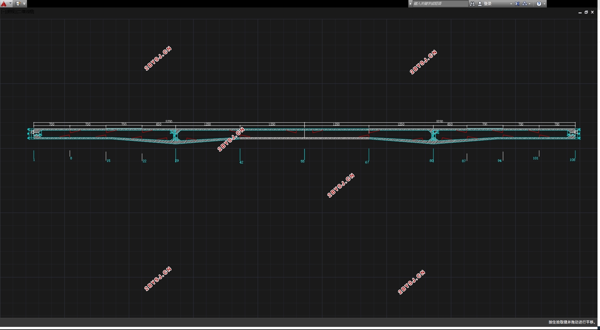
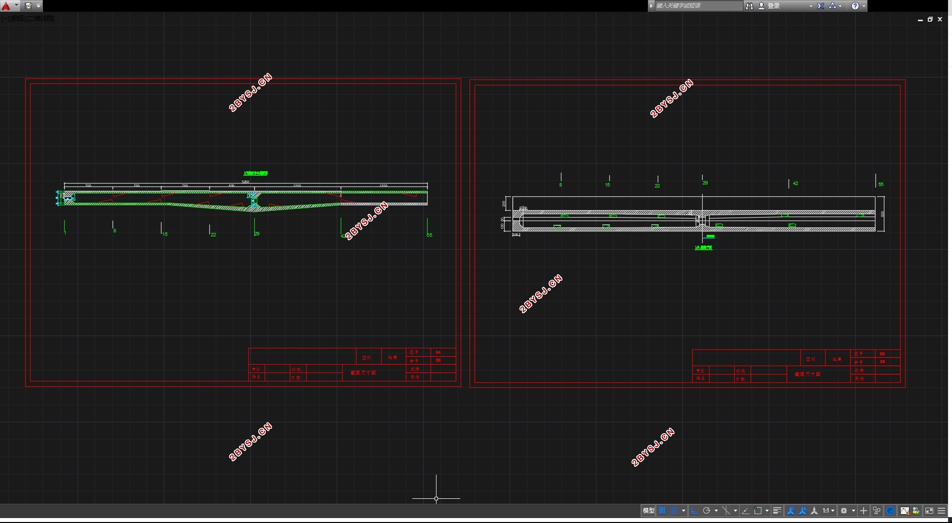
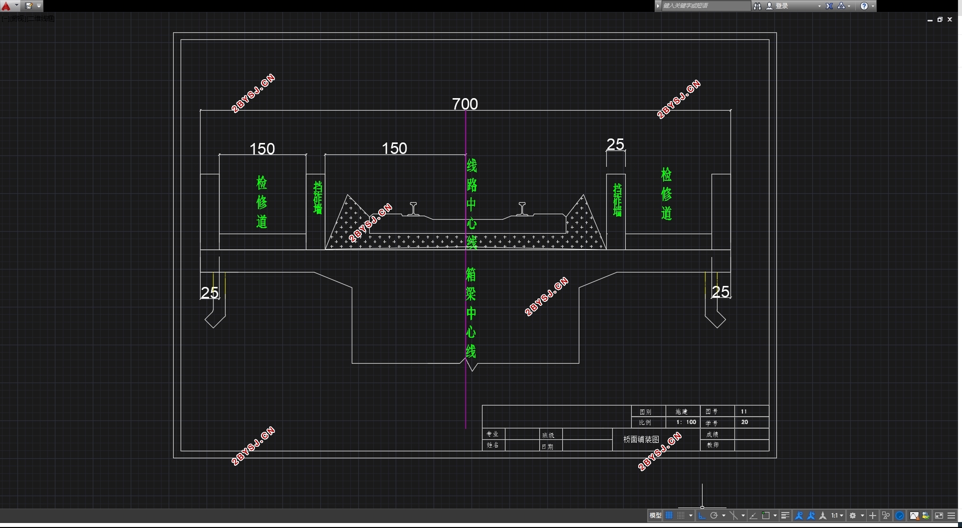
本计算书是针对标段中的27.5+50+27.5米的预应力混凝土连续梁桥进行。桥宽为7m,采用单箱单室,单侧翼板长1.5米;梁高为2~3米,梁底按二次抛物线型变化。
箱梁腹板采用斜腹板,腹板的厚度随着剪力的增大而从跨中向支点逐渐加大,箱梁边腹板厚度为50~60cm。箱梁顶板厚30cm。为了满足支座布置及承受支点反力的需要,底板的厚度随着负弯矩的增大而逐渐从跨中向支点逐渐加大,厚度为30cm。其中跨跨中断面形式见图1.1,支承横梁边的截面形式见图1.2。结构支承形式见图1.3。主梁设纵向预应力。钢束采用Øj15.24低松弛预应力钢绞线,标准强度为1860MPa,弹性模量为1.9X10⁵ MPa,公称面积为140mm2。预应力钢束采用真空吸浆工艺,管道采用与其配套的镀锌金属波纹管。纵向钢束采用大吨位锚。钢束为20Øs15.24的钢绞线,均为两端张拉,张拉控制应力为1339MPa。


目 录 1
第一章 摘要 3
第二章 结构尺寸拟定 5
2.1 总体布置 5
2.2 细部尺寸拟定 5
2.3 本桥主要材料 7
2.3.1混凝土: 7
2.3.2预应力钢绞线: 7
2.3.3箍筋: 7
第三章 预应力混凝土连续梁桥内力计算 8
3.1 计算模型建立 8
3.1.1 节点对应截面 8
3.1.2支座布置 8
3.2 毛截面几何特性计算 9
3.3 恒载内力计算 9
3.3.1计算方法 9
3.3.2 控制截面选择 9
3.3.3 恒载取值 10
3.3.4 10
3.3.5 10
3.3.6控制截面恒载内力 10
3.4 活载内力计算 12
3.4.1移动荷载 12
3.4.2活载内力影响线及加载图式 12
3.4.3控制截面的活载内力 19
3.4基础沉降引起的内力计算 20
3.5 温度及支座沉降次内力计算 21
3.5.1温度次内力计算 21
3.6 内力组合 23
3.6.1主力组合 23
3.6.2主力+附加力组合 24
第四章 主梁配筋 26
4.1 预应力钢筋数量的估算 26
4.1.1估算方法 26
4.2预应力筋估算 28
4.3 预应力束筋的布置 33
二、 钢束的布置 34
根据前面的各截面钢束配置,钢筋全采用20根一束 34
第五章 主梁验算 35
5.1 截面几何特性 35
一、计算方法 35
二、换算截面几何特性计算 36
5.2正截面抗弯验算 37
5.3 斜截面抗剪验算 38
——计算主应力点处构件截面宽度( )。 39
5.4运营阶段正截面抗裂验算 39
5.5 混凝土压应力验算(运营阶段) 41
5.6预应力钢筋应力幅验算(运营阶段) 43
5.7 预应力钢筋锚下控制应力验算(传力锚固阶段) 46
5.8混凝土剪应力验算(运营阶段) 49
5.9混凝土法向应力验算(传力锚固阶段) 49
结论 51
