
某综合楼建筑给水排水工程设计(含CAD图)
无需注册登录,支付后按照提示操作即可获取该资料.
某综合楼建筑给水排水工程设计(含CAD图)(任务书,开题报告,外文翻译,设计说明书20000字,CAD图20张)
摘 要
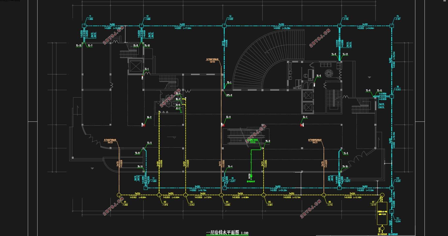
本建筑工程为某商业大楼,给水系统分区供水,地下负一到地上三层为低区,由市政管网直接供水,四层到八层为高区,采用一组调速泵供水。生活排水采用污、废水合流制,一二层为商业部分,污水排水立管在二层的吊顶自排水横干管汇集到主立管再引出至室外污水井;三层及以上楼层为办公写字楼,休息室卫生间排水各层通过排水横管排至立管,由立管汇集至下;地下室内雨污水通过地下排水渠汇集至集水坑,由集水坑内污水提升泵加压提升,排至室外污水管道。屋面雨水排放选外排水排放方式,雨水经屋面雨水斗收集后由雨水管排至检查井。
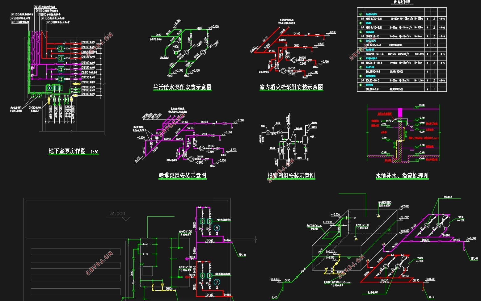
根据规范,该建筑为二类高层建筑,室外消火栓用水量20L/s,室内消火栓用水量30L/s,火灾延续时间2h。消火栓充实水柱高度12m,水龙带长度25m,水枪喷嘴流量5.16L/s,消防立管管径为DN100。在屋顶层设试验消火栓一个,每个室内消火栓箱内均设有远距离启动消防泵的按钮。
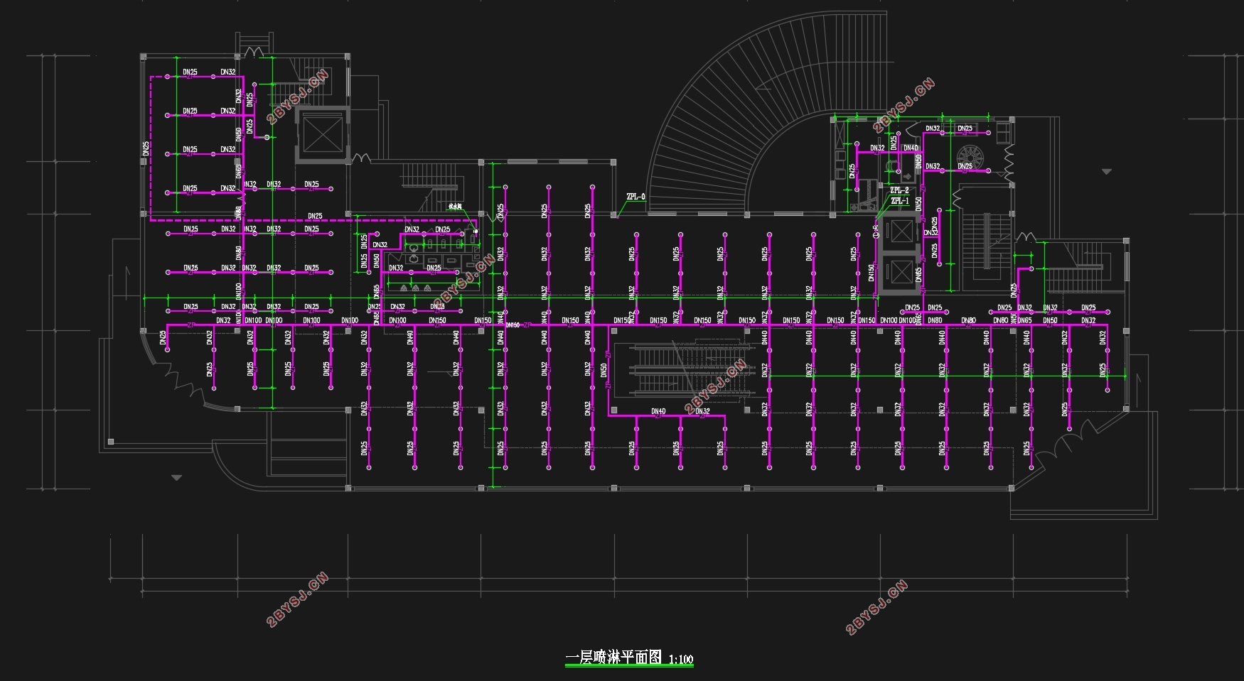
该建筑采用湿式自动喷淋灭火系统,报警阀设于地下一层,各层均设水流指示器、末端试水装置和信号阀,其信号均送入消防控制中心进行处理。本工程的自动喷水灭火系统分2个区。屋顶水箱为18立方米为消防水箱,贮存10min自动喷水灭火系统、室内消火栓系统用水量。自动喷水灭火系统和消火栓系统的初期灭火由水箱供水,后期供水由地下室的消防水泵和自喷泵供水。
关键词:给水系统、排水系统、消火栓系统、自动喷水灭火系统、雨水系统
Abstract
The construction project is a commercial building, water system zoning water, underground negative one to three layer for low area, by the municipal water supply pipe network directly, four to eight layer for the area, using a set of variable speed pump water supply. Life drain the sewage, wastewater confluence, a two-story as part of the business, sewage drainage riser in the second layer of the ceiling from horizontal drainage dry collection pipe to the main vertical pipe and then leads to outdoor sewage well; three layer and above the floor for office office, room toilet drainage layers by horizontal drainage pipe row to riser, consists of a riser is collected to the next; in the basement of the rain sewage by subsurface drains together to the sump and the puddle of sewage lifting pump pressure lifting, discharged to the outdoor sewage pipe. Roof drainage drainage discharge mode selection, the rainwater collected from the roof drain rain water pipe row to check well.
According to the specification, the building is the second class of high-rise buildings, outdoor fire hydrant water 20L / s, indoor fire hydrant water is fire continue time 2H. The fire hydrant to enrich the water column height 12M, length 25m hose, gun nozzle flow 5.16L/s, riser diameter is DN100. On the roof floor test a fire hydrant, fire hydrant box each are equipped with remote start the fire pump button.
The building adopts wet automatic sprinkler system, alarm valve is located in the ground floor, each layer has a water flow indicator, the end of the test water device and signal valve, the signal is sent to the fire control center for processing. The automatic water spraying fire extinguishing system in this project is divided into 2 zones. The roof water tank of 18 cubic meters for the fire water tank, fire water storage 10min automatic sprinkler system, indoor fire hydrant system. Automatic sprinkler system and fire hydrant system of early fire extinguishing by water supply and post water from the basement of the fire pump and sprinkler pump water supply.
Keyword: water-supply system、drainage system、hydrant system、automatic sprinkler system、rainwater system

目录
第一章 设计方案比选及说明
一、给水系统 1
1.1给水方案 1
1.1.1方案选择 1
1.1.2方案选择依据 2
1.2给水系统组成 2
1.3给水管道的布置与敷设 2
二、消防系统 4
2.1室内消火栓系统 4
2.1.1室内消火栓系统的选择 4
2.1.2系统组成 4
2.1.3设备及构筑物 4
2.1.4消火栓的安装 5
2.2自动喷淋系统 5
2.2.1室内自动喷水灭火系统的选择 5
2.2.2系统组成 5
2.2.3喷头的选择与布置 6
2.2.4设备及构筑物 7
2.2.5喷淋系统的安装 7
三、室内排水系统 7
3.1系统选择 7
3.2系统组成 8
3.3主要设备及构筑物 8
3.4排水管道安装要求 8
3.5通气管安装要求 8
3.6清扫口、检查口安装要求 9
四、雨水系统 10
4.1雨水排水系统的选择 10
4.2雨水排水系统的组成 10
4.3雨水管道的敷设与布置 10
第二章 设计计算书 12
一、给水系统的计算 12
1.1用水量计算 12
1.2室内给水管网水力计算 13
1.3设备的计算与选择 17
1.4生活贮水池容积计算 19
二、排水系统的计算 12
2.1卫生器具排水定额及排水管道设计秒流量公式的确定 19
2.2建筑内排水管道计算 20
2.3地下室排水系统计算 26
2.5化粪池设计计算 26
三、消火栓系统的计算 27
3.1室内消火栓系统计算 27
3.2室内消火栓系统屋顶增压设施设计 31
3.3减压孔板设计 32
3.4水泵接合器设置 34
3.5消防水箱 34
3.6消防贮水池 35
四、自动喷水与灭火系统的计算 36
4.1自动喷水灭火给水系统计算 36
4.2喷淋系统屋顶增压设施设计 44
4.3减压孔板计算 45
五、建筑雨水排水系统的计算 46
5.1降雨强度的确定 46
5.2雨水立管的布置 46
5.3雨水水力计算 47
六、室外排水系统的计算 48
6.1室外污水水力计算 48
6.2室外雨水水力计算 48
附表1和附表2 50
参考文献 51
致谢 52