恩施某23m空心板桥结构设计(含CAD图)
无需注册登录,支付后按照提示操作即可获取该资料.
恩施某23m空心板桥结构设计(含CAD图)(任务书,开题报告,论文计算书21000字,CAD图25张)
摘 要
恩施某空心板桥结构设计主要包括设计计算说明书和图纸绘制两部分,其中计算说明书主要包括前两上部结构的设计和下部结构的设计及相应钢筋的配置校核,图纸应包括桥梁整体布置图,上下部各结构构造图及相应的钢筋配置图。
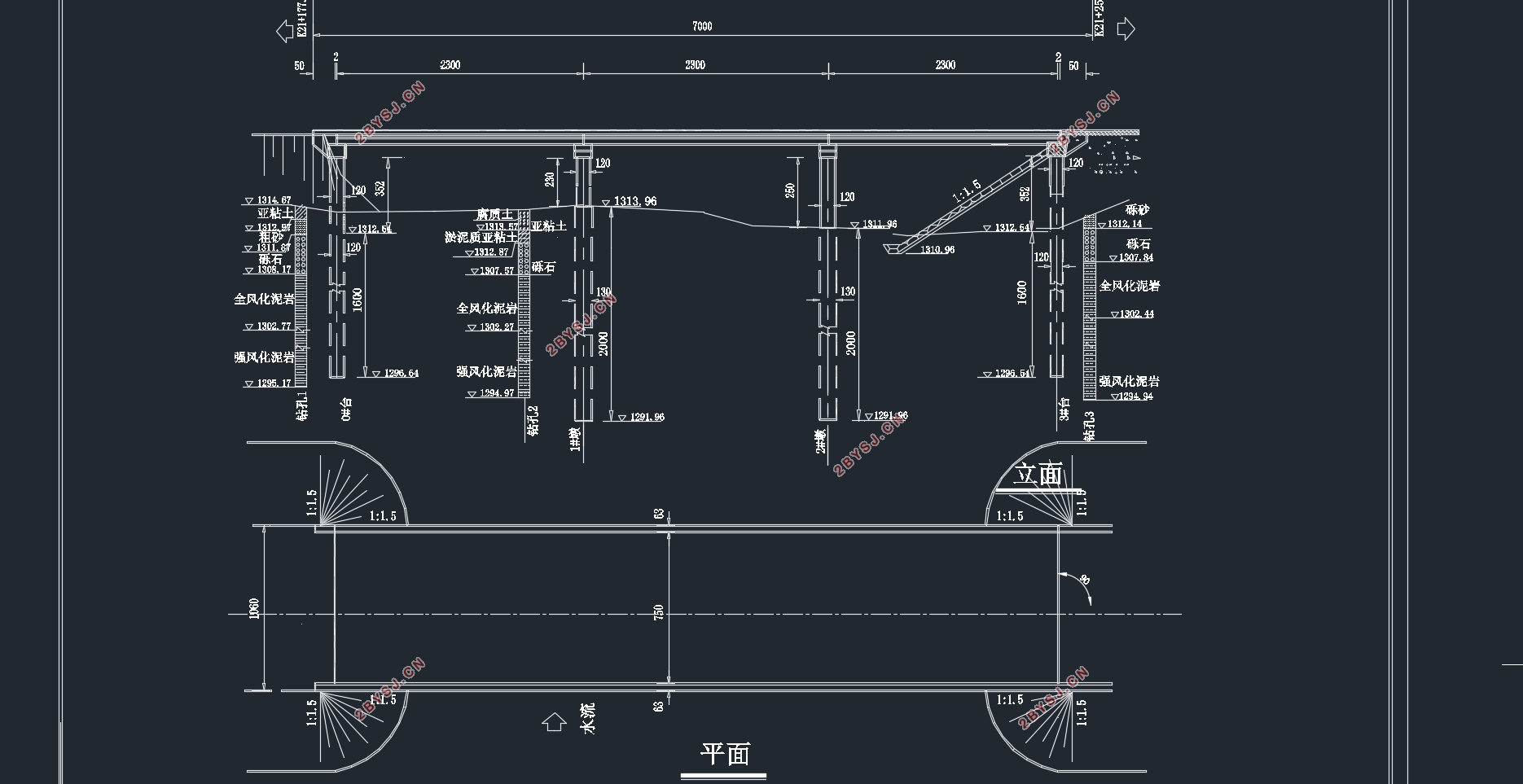
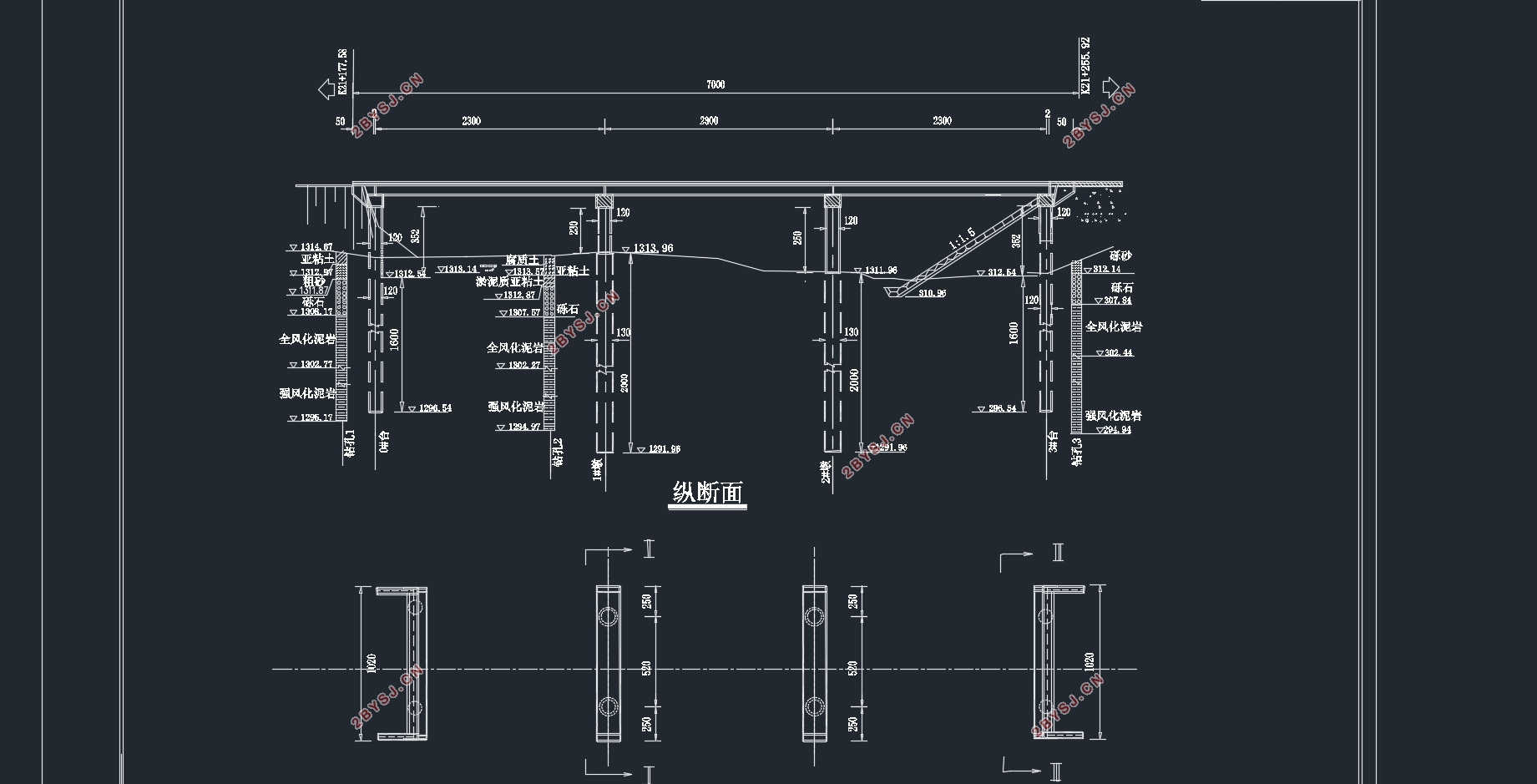
恩施某空心板桥桥跨结构为3x23m预制空心板,桥主体总长69m,结构形式为先简支后桥面连续。设计荷载为公路一级,整体采用双向四车道,结构对称,双向车道及桥体采用分离式,因此本设计中只对桥的半幅进行设计。单项桥面总宽10.6m,由六块1.14m宽的中板和两块1.77m宽的边板组成,共计八块板。下部结构采用圆柱式桥墩,桩基础为20m深的钻孔灌注桩,为端承桩。
本计算书主要对桥梁空心板进行结构设计与计算校核,大致步骤如下:先对桥型进行选择并确定板的截面尺寸,然后进行桥梁上部结构的设计,主要包括内力计算,配筋计算,强度验算,预应力损失验算以及变形验算等。下部结构设计主要包括桩基础的配筋设计及承载能力验算。
Abstract
Enshi mainly includes the design of a hollow slab bridge structure design and calculation specification and drawing of two parts, including computing instruction mainly includes the design of the first two upper structure and lower the design of the structure and the corresponding reinforcement configuration, drawings should include the overall layout of bridge, top and bottom of each structure diagram and the corresponding reinforcement configuration diagram.
The span structure of a hollow slab bridge in enshi is 3x23m prefabricated hollow slab. The main body of the bridge is 69m in length. The design load is the first level of the highway, and the whole structure is symmetrical with four lanes of two-way road. The two lanes and the bridge body are separated, so only half of the bridge is designed in this design. The total width of the single bridge deck is 10.6m, consisting of six 1.14m wide middle plates and two 1.77m wide side plates, totaling eight plates. The bottom structure adopts cylindrical bridge piers, and the pile foundation is a bored pile with a depth of 20m, which is the end bearing pile.
The calculation is mainly carried out on the hollow slab bridge structure design and calculation, general steps are as follows: first to select bridge and determine the section size of plate, and then to the design of the bridge superstructure, mainly including internal force calculation, reinforcement calculation, strength calculation, loss of prestress calculation and deformation calculation, etc. The structural design of the lower part mainly includes the reinforcement design of pile foundation and the calculation of bearing capacity.
3.1设计标准
(1)跨径:标准跨径为23m;伸缩缝单元宽度取80mm,预制板长取22.92m;支座中心线距离梁端取50cm,计算跨径取21.92m;
(2)桥面净宽分布:0.6m防撞墙,2.0m人行道,7.5m机动车道,1.0m分隔带,7.5m机动车道,2.0m人行道,0.6m防撞墙;
(3)设计荷载:公路-Ⅰ级,人群荷载按规范取 ;
(4)桥梁上部结构:3×23m装配式预应力空心板梁。
3.2设计资料
(1)上部结构:C50预制预应力混凝土空心板。
(2)墩柱:墩柱采用C30现浇钢筋混凝土结构,
(3)盖梁:盖梁采用C40现浇钢筋混凝土结构;
(4)水文地质情况:地下水及地表水对混凝土结构、钢筋混凝土结构中钢筋无腐蚀性;
(5)其它标准:防震设计按地震按动峰值加速度0.05g进行设防,风力影响等要素按相关规范采用。
3.3设计要点
(1)本空心板构件按A类构件进行裂缝和拉压应力的控制验算,桥面铺装层分为两层,分别为100mm的C40混凝土和100mm的沥青混凝土,并配置相应的钢筋网。
(2)构件混凝土的强度需达到标准抗压强度的85%时才许放张预应力钢筋;
(3)计算混凝土收缩和徐变引起的预应力损失按锚固龄期为7天时取值计算;
(4)建筑环境平均相对湿度RH取80%;
(5)施工阶段应注意空心板预制保存时间为90d。


目 录
第1章 绪论 1
第2章 概述 2
2.1方案的选择 2
2.2基本设计资料 2
2.3空心板设计特性计算 2
第3章 设计资料 4
3.1相关设计资料 4
3.2设计规范依据 4
3.3设计要点 4
第4章 构造形式及截面尺寸的拟定 5
第5章 内力计算 9
5.1跨中横向分布系数的计算 9
5.2支点横向分布系数计算 12
5.3作用效应的计算 12
5.4汽车荷载冲击系数计算 13
5.5作用效应的计算 14
5.5.1永久作用效应 14
5.5.2可变作用效应 14
5.5.3作用效应组合 20
第6章 钢筋面积的估算及布置 28
6.1预应力钢筋所需面积和数量的估算 28
6.2预应力钢筋的截面布置 29
6.3非预应力钢筋的估算及布置 29
6.4箍筋的设计 30
6.4.1空心板截面尺寸的检查 30
6.4.2检查并进行箍筋计算 31
6.4.3箍筋的计算 31
6.5换算截面的几何特性计算 32
第7章 空心板强度计算 36
7.1跨中截面正截面抗弯承载力计算 36
7.2斜截面抗剪承载力计算 36
7.2.1截面抗剪强度上限与下限的复核(边板) 36
7.2.2斜截面抗剪承载力计算 38
第8章 预应力损失的估算 39
8.1预应力钢筋与管壁之间的摩擦产生的应力损失 39
8.2锚具由于变形、回缩引起的应力损失 39
8.3预应力钢筋与台座之间的温差引起的应力损失 39
8.4预应力钢绞线由应力松弛引起的预应力损失 39
8.5混凝土由于弹性压缩引起的预应力损失 40
8.6混凝土收缩、徐变引起的预应力损失 40
8.7预应力损失的组合 45
第9章 应力验算 48
9.1施加预应力阶段空心板截面应力的验算 48
9.2使用阶段空心板截面应力的验算 52
第10章 空心板变形验算 55
10.1正常使用阶段的扰度计算 55
10.2 预加力引起的反拱度计算及所需预拱度的设置 55
第11章 迈达斯模型电算 62
第12章 下部结构设计 71
12.1设计数据 71
12.1.1 设计标准及上部构造 71
12.1.2 支座的选择 71
12.1.3 水文,地质条件 71
12.1.4 材料设计 71
12.2板式橡胶支座的计算 71
12.2.1支座的平面尺寸拟定 71
12.2.2支座的厚度计算 72
12.2.3验算支座的偏转情况 72
12.2.4验算支座底部的抗滑稳定性 73
12.3盖梁计算 73
12.3.1 尺寸的拟定 73
12.3.2荷载及荷载效应计算 74
12.3.3截面配筋设计与承载力校核 79
12.4墩柱的设计 83
12.4.1荷载计算 83
12.4.2截面配筋计算 84
12.5桩基设计 88
12.5.1荷载计算 88
12.5.2桩长设计 89
12.5.3桩基配筋设计及强度验算 90
参考文献 92
致谢词
