EQ1092F1型长头柴油载货汽车驱动桥设计(含CAD图,CATIA三维图)(英文)
无需注册登录,支付后按照提示操作即可获取该资料.
EQ1092F1型长头柴油载货汽车驱动桥设计(含CAD图,CATIA三维图)(英文)(任务书,开题报告,外文翻译,论文说明书英文7000字,CAD图4张,CATIA三维图)
Abstract
Driving axle is in the end of transmission department of power, which is used to increase the torque that comes from gearbox, and distributes power reasonably. In addition, it bears vertical force, longitudinal force and lateral force from road surface and frame. Normally, driving axle consists of final drive, differential, half-shaft and axle housing.
There are two types of driving axle: disconnecting type and non-disconnecting.
For non-disconnecting type, its driving axle is connected with wheel through suspension. Since half-shaft collect and final drive are linked to be an integral part, it is impossible to find a relative motion between half-shaft and driving wheels in horizontal space. So this kind of driving axle is called non-disconnecting type, which is also called integral driving axle.
In order to increase automobile driving comfort and traffic ability, many cars use independent suspension nowadays, which means drive wheels of two sides use flexible suspension connected with frame respectively, so that two wheels may bounce independently. Corresponding with this, for disconnecting type, the shell of final drive is fixed on frame. The shell of driving axle is manufactured into sections and finally joined through hinges.
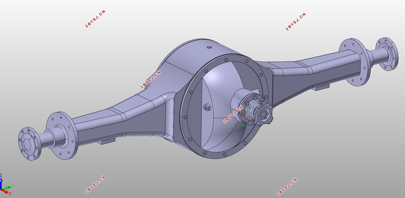
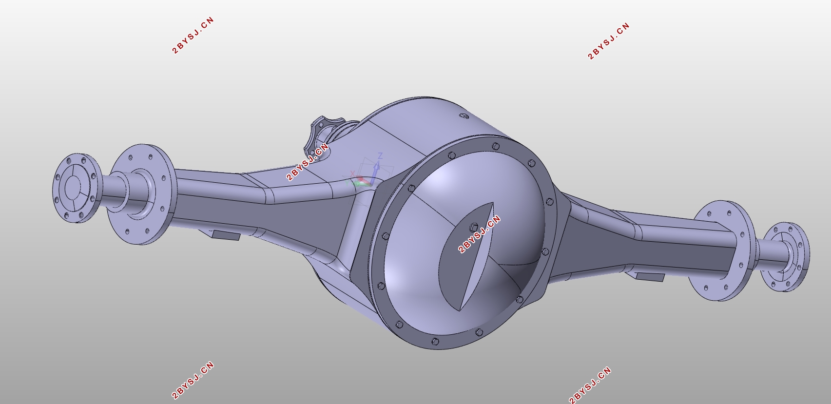
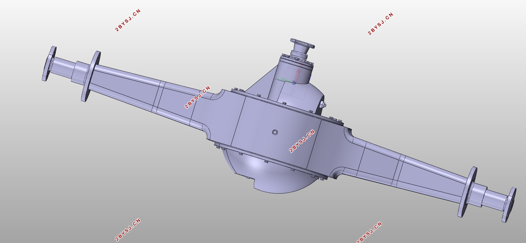
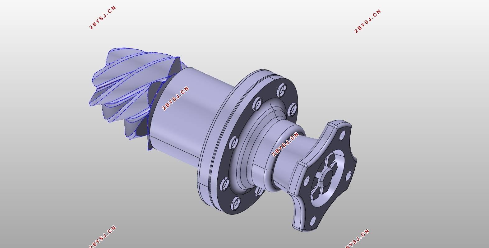
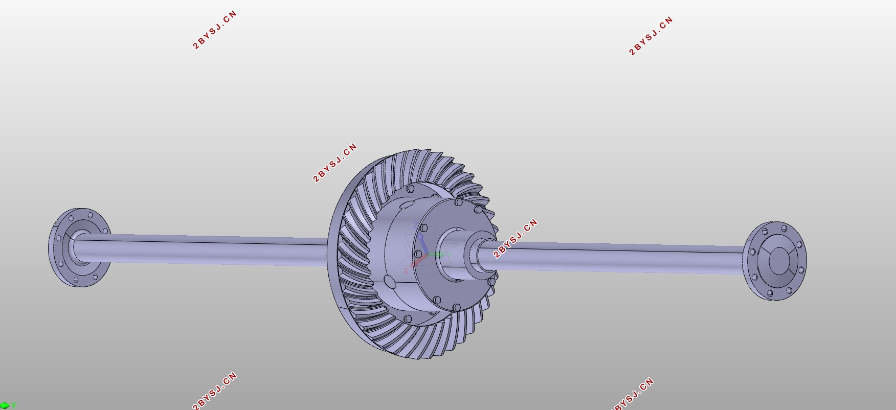
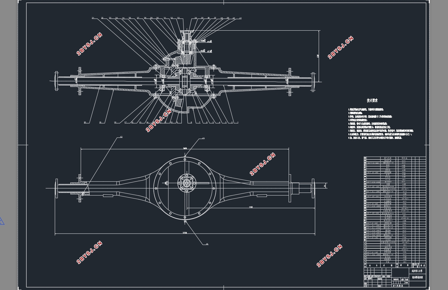
According to the truck type—Dongfeng EQ1092F1, this design will choose non-disconnecting type of driving axle, using single-class hypoid bevel gear final drive, symmetric planetary gear differential, full-floating half-shaft and integral driving housing.
Key Words:driving axle design;hypoid bevel gear;full-floating half-shaft;final drive

CONTENT
Chapter 1 Introduction
1.1 Purpose and Significance 1
1.2 Analysis of Research Status at Home and Abroad 1
Chapter 2 Analysis of Driving Axle Structure
2.1 Summarize 3
2.2 Structure of Driving Axle 3
Chapter 3 Final Drive Design
3.1 Structure of Final Drive 7
3.1.1 Type of Gear 7
3.1.2 Deceleration Form 7
3.1.3 Support Arrangement of Gears 7
3.2 Basic Parameter Design 8
3.2.1 Final Ratio 8
3.2.2 Load Calculation 9
3.2.3 Basic Parameters For Hypoid Gear 11
3.2.4 Geometric Dimensions of Hypoid Gear 15
3.2.5 Strength Check For Hypoid Gear 17
3.2.6 Material and Heat Treatment 20
Chapter 4 Differential Design
4.1 Principle of Symmetrical Bevel Gear Differential 21
4.2 Structure of Symmetrical Bevel Gear Differential 23
4.3 Symmetrical Bevel Gear Differential Design 23
4.3.1 Basic Parameter Design 23
4.3.2 Geometric Dimensions of Differential Gear 26
4.3.3 Strength Check For Differential Gear 29
Chapter 5 Half-shaft Design
5.1 Load Calculation 30
5.2 Diameter Design 31
5.3 Strength Check For Half-shaft 32
5.4 Strength Check For Half-shaft Spline 32
Chapter 6 Driving Axle Housing Design
6.1 Basic Requirements 34
6.2 Finite Element Analysis 35
Reference 36
Acknowledgements 37
Appendix 38
