东风风神A60手动变速器设计(含CAD零件装配图,CATIA三维图)
无需注册登录,支付后按照提示操作即可获取该资料.
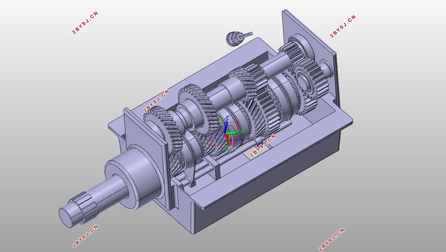
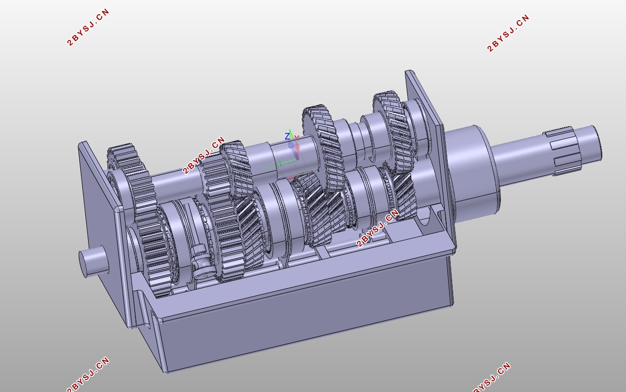
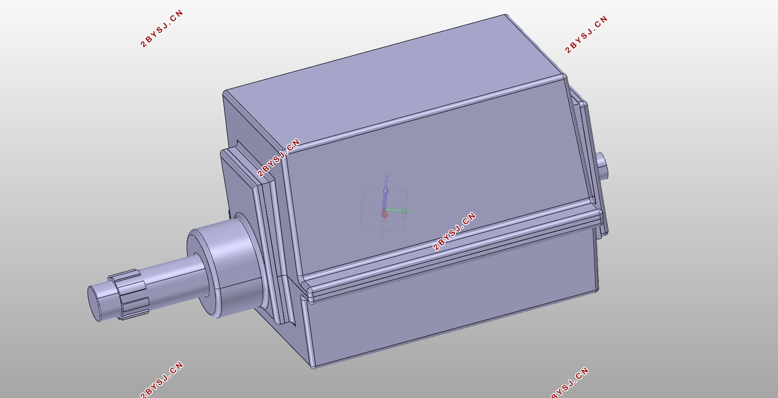
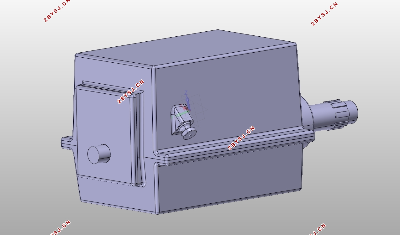
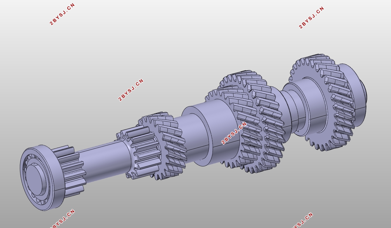
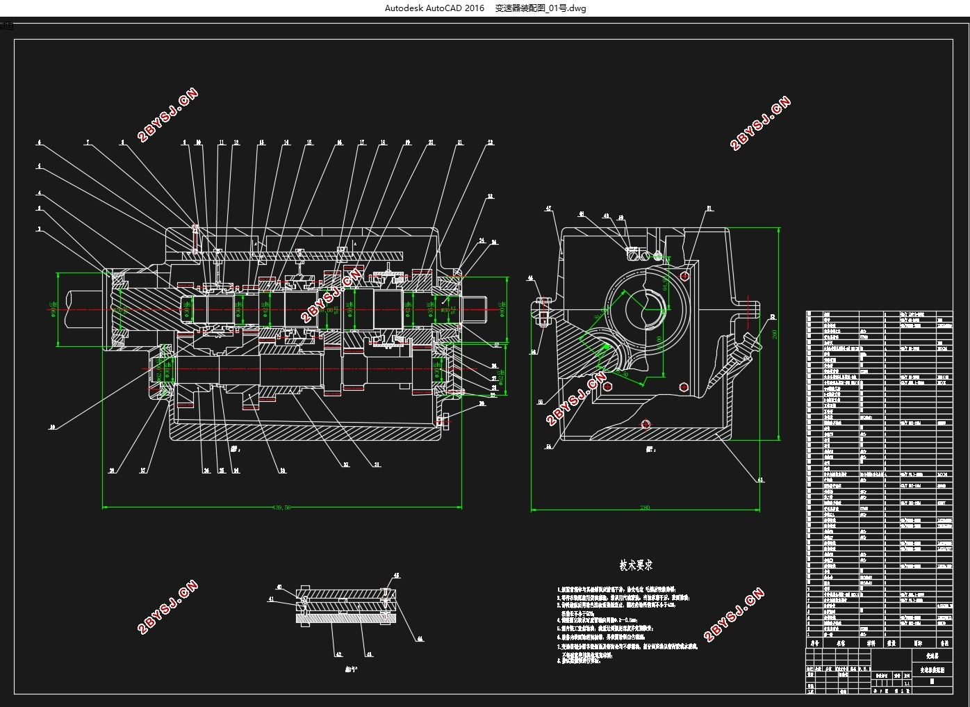
东风风神A60手动变速器设计(含CAD零件装配图,CATIA三维图)(任务书,开题报告,文献摘要,外文翻译,论文说明书10000字,CAD图7张,CATIA三维图)
摘要
变速器是汽车动力总成的重要组成部分,对整车的动力性,燃油经济性和舒适性都有重要影响。其上承发动机,下启驱动轮。通过改变传动比,变速器可以将来自发动机的动力转变成载具在不同路况下所需的驱动力;它也可以利用空档来中止动力转递,或使发动机轻松启动;它还可实现车辆倒退行驶。
本次设计的基础数据来自东风A60手动变速器的维修手册,其内容包括主减速比,最高时速,扭矩及其相应的转速,发动机型号,轮胎规格等。通过合理利用上述数据,在规定时间内完成机械式手动变速器的设计。在这期间根据先初步确定了传动机构的布置方案,初步选定了诸如档位数,各档齿轮的传动比,模数等变速器的主要参数,然后对齿轮,轴,轴承及键进行详细的计算校核,最后对同步器,操纵机构及箱体的进行设计。
关键词: 变速器;机械式;设计;齿轮;轴;
Abstract
The transmission is an important part of the automobile powertrain, and has an important impact on the vehicle's power, fuel economy and comfort . Its upper engine, lower drive wheel, by changing the transmission ratio, the transmission can convert the power provided by the engine into the required driving force under different road conditions; it can use the neutral gear to interrupt the power transfer, start the engine; it also Reverse gear can be achieved.
The base data of this design is provided in the maintenance manual of the Dongfeng A60 manual transmission. The content includes the main reduction ratio, the maximum speed, the torque and the corresponding rotation speed, the engine model, and the tire specifications.By using above data in a special period of time,Complete the design of the mechanical manual transmission. During this period, the layout of the transmission mechanism was initially determined. At the same time, the main parameters such as number of gears, transmission ratio of each gear, gear module, etc. were selected, and then the gears, shafts, bearings and keys were detailed. Calculation, check. Finally, the synchronizer, operating mechanism and box are designed.
Key Words: Transmission; Mechanical; Design; Gears; Shafts;

目录
摘要 I
Abstract II
目录 1
第1章 绪论 1
1.1研究目的和意义 1
1.2 研究现状和发展 1
第2章 变速器传动机构布置方案设计 3
2.1变速器类型选择 3
2.2倒挡形式选择 3
2.3齿轮形式 4
2.4换挡机构 4
2.5轴承及键的选择 5
第3章变速器主要参数的选择及校核 6
3.1变速器挡位选择 6
3.2变速器各挡传动比的确定 6
3.2.1 依据汽车最大爬坡度确定 6
3.2.2 根据驱动车轮与路面的附着条件确定 7
3.3变速器中心距 8
3.4机械式变速器的轴向尺寸 8
3.5齿轮的参数 9
3.5.1 齿轮模数 9
3.5.2 压力角 9
3.5.3 螺旋角 9
3.5.4 齿宽 9
3.5.5 齿顶高系数 10
第4章 齿轮设计计算与校核 11
4.1 各挡齿轮的齿数分配计算 11
4.1.1 一挡齿轮的齿数 11
4.1.2 确定常啮合传动齿轮的齿数 12
4.1.3 确定二挡齿轮的齿数 13
4.1.4 确定三挡齿轮的齿数 13
4.1.5 确定五挡齿轮的齿数 14
4.1.6 确定倒挡齿轮的齿数 14
4.2 计算各轴转矩与齿轮的受力情况 15
4.2.1 .计算各轴的转矩 15
4.2.2 .计算各挡齿轮的受力 16
4.3 轮齿材料选择 16
4.4 轮齿强度计算 16
4.4.1 轮齿弯曲强度计算 17
4.4.2 轮齿接触应力 20
第5章 轴设计计算与校核 22
5.1 轴的结构 22
5.2 轴的尺寸 22
5.3 轴的校核 22
5.3.1 轴的刚度验算 22
5.3.2 轴的强度计算 27
第6章 轴承及键的设计计算与校核 30
6.1 轴承使用寿命 30
6.2 第一轴轴承的选择与校核 30
6.2.1 当量动载荷计算 30
6.2.2 计算轴承基本额定寿命 31
6.3 第二轴轴承的选择与校核 31
6.3.1 当量动载荷计算 32
6.3.2 计算轴承基本额定寿命 32
6.4 中间轴轴承的选择与校核 32
6.4.1 当量动载荷计算 32
6.4.2 计算轴承基本额定寿命 33
6.5 键设计计算与校核 33
6.5.1 键的选取 34
6.5.2 平键的校核 34
6.5.3 花键的校核 35
第7章 同步器及操纵机构 36
7.1 同步器结构设计 36
7.2 操纵机构结构设计 37
第8章 箱体设计 39
8.1 箱体材料与毛坯种类 39
8.2 箱体的主要结构尺寸的计算 39
第9章 总结 40
参考文献 41
附录A 42
附录B 43
致 谢 46
