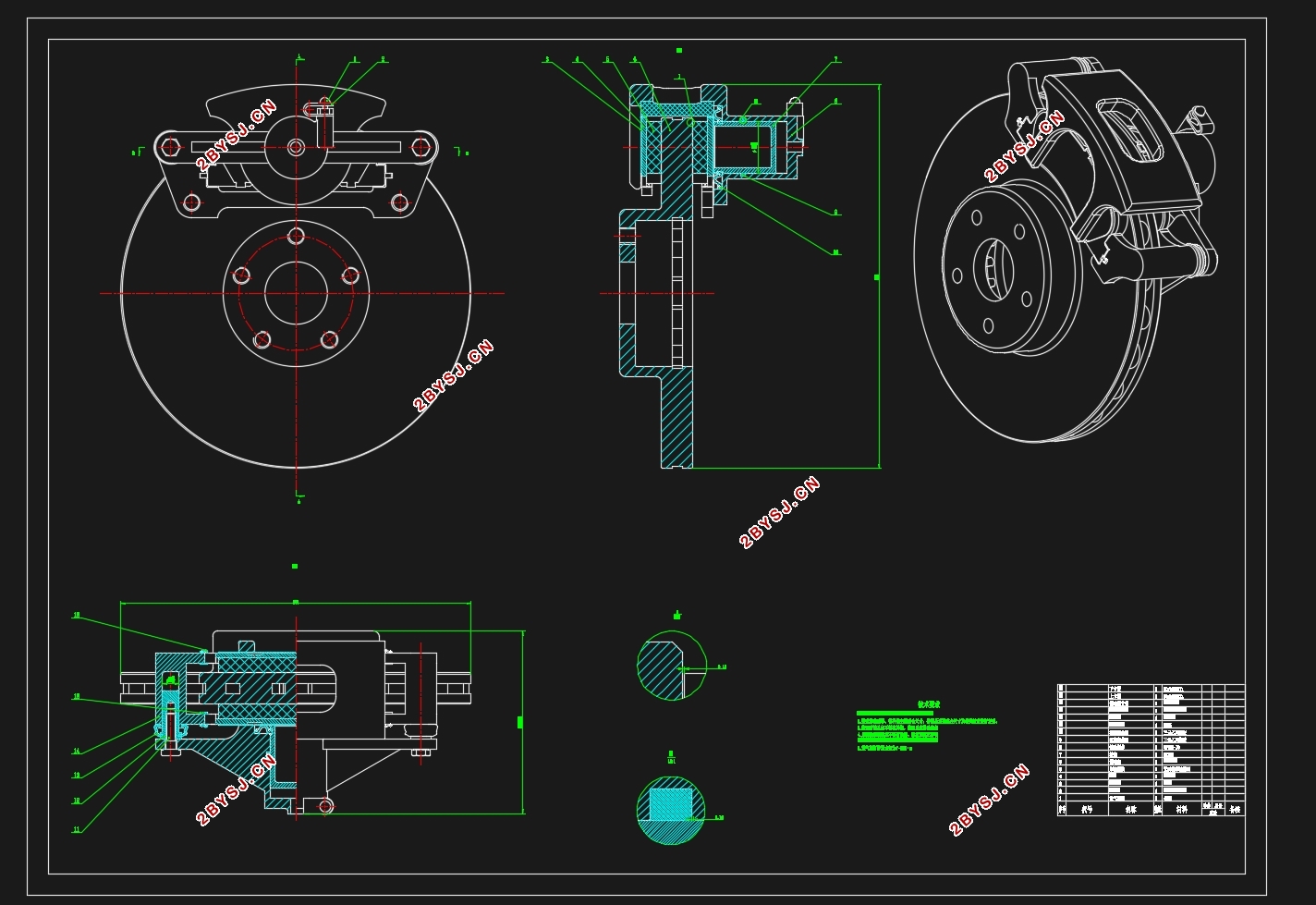
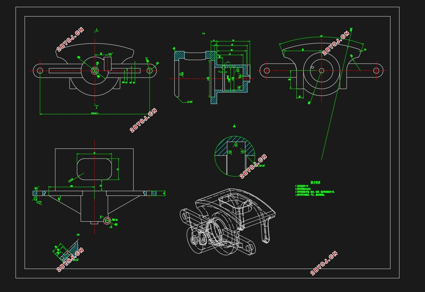
宝骏560制动器制动系统设计(含CAD零件图装配图)
无需注册登录,支付后按照提示操作即可获取该资料.
宝骏560制动器制动系统设计(含CAD零件图装配图)(任务书,开题报告,文献摘要,外文翻译,论文说明书13000字,CAD图9张)
摘要
随着科学技术的不断发展,汽车的行驶速度在不断提高,并且汽车保有量的增长也带来了车流密度的增大,从而引发的交通事故也越来越多。为了确保人和车辆的安全,就必须保证车辆有良好的制动性能,为汽车设计一个可靠的制动系统。
该次设计首先对制动器的设计方案整体进行了论证与选择,主要包括制动器结构形式与选择、盘式制动器的结构形式与选择、制动驱动机构的选择、制动管路的选择和制动器间隙自动调整装置的设计,最终确定为液压双回路滑动钳盘式制动器。然后根据汽车的已知参数,确定出制动器的主要参数,包括制动力与制动力分配系数、同步附着系数、制动器制动力矩、利用附着系数和制动效率。最后对制动器的主要部件进行参数与结构上的设计,并且进行校核。
关键词:盘式制动器;制动系统;液压制动
Abstract
With the development of science and technology, the driving speed of the car is increasing, and the growth of car ownership also brings the increase of the density of traffic, which leads to more and more traffic accidents.In order to ensure the safety of people and vehicles, it is necessary to ensure that the vehicle has good braking performance, and to design a reliable braking system for the automobile.
About this design, firstly,I demonstrate and select the design of the brake, mainly including the form of brake, the form of disc brake, the selection of brake drive mechanism, the selection of brake pipe and the design of automatic adjusting brake clearance, the design of the final determination scheme adopts sliding caliper disc brake with dual-circuit hydraulics braking system. And then, I determine the main parameters of the brakes based onthe known parameters of the vehicle, including braking force and braking force distribution coefficient, synchronous adhesion coefficient, the braking torque, utilization of adhesion coefficient and braking efficiency. Finally, I finish the determination of the brake main parameters and the design and check of main parts.
Keywords: disc brake,brake system, hydraulic brake
宝骏560车型设计参数:
整备质量:1370kg
总质量:1780kg
轴距:L=2750mm
前轴负荷:G1=885kg
后轴负荷:G2=895kg
质心距前轴的距离:L_1=895⁄1780×2750=1382.7mm
质心距后轴的距离:L_2=885⁄1780×2750=1367.3mm
质心高度:hg=650mm
车轮有效半径:r_e=((215×60%×2+17×25.4))⁄2=344.9mm


目录
摘要 I
Abstract II
第1章绪论 1
1.1制动系统的设计意义 1
1.2制动系统概述 1
1.3设计任务 2
第2章制动器设计方案的论证与选择 3
2.1制动器的设计要求 3
2.2制动器设计时应考虑的性能要求 3
2.3制动器的结构形式与选择 4
2.3.1制动器的主要类型 4
2.3.2制动器的工作原理 4
2.3.3方案的比较与确定 5
2.4盘式制动器的结构形式及选择 6
2.5制动驱动机构的选择 7
2.6制动管路的选择 7
2.7制动器间隙自动调整装置 8
第3章制动器的主要参数 10
3.1制动力与制动力分配系数 10
3.2同步附着系数 13
3.3前后轮制动器的制动力矩 13
3.4利用附着系数和制动效率 14
第4章制动器的设计计算 16
4.1制动盘主要参数的确定 16
4.1.1制动盘直径D 16
4.1.2制动盘厚度h 16
4.2摩擦衬块主要参数的确定与设计计算 16
4.2.1摩擦衬块内半径和外半径 16
4.2.2摩擦衬块工作面积 17
4.2.3摩擦衬块的磨损特性计算 17
4.3液压制动驱动机构的设计计算 18
4.3.1制动轮缸直径与工作容积 18
4.3.2制动主缸直径与工作容积 19
4.3.3制动踏板力 19
4.3.4踏板工作行程 20
4.4盘式制动器制动力矩计算 20
4.5应急制动和驻车制动的制动力矩 21
第5章制动器的结构设计与强度计算 24
5.1制动盘 24
5.2制动钳 24
5.3制动块 25
5.4摩擦材料 25
5.5制动器热容量和温升的核算 25
第6章总结 27
参考文献 28
致谢 29
