煤油冷却器的设计(含CAD零件图装配图)
无需注册登录,支付后按照提示操作即可获取该资料.
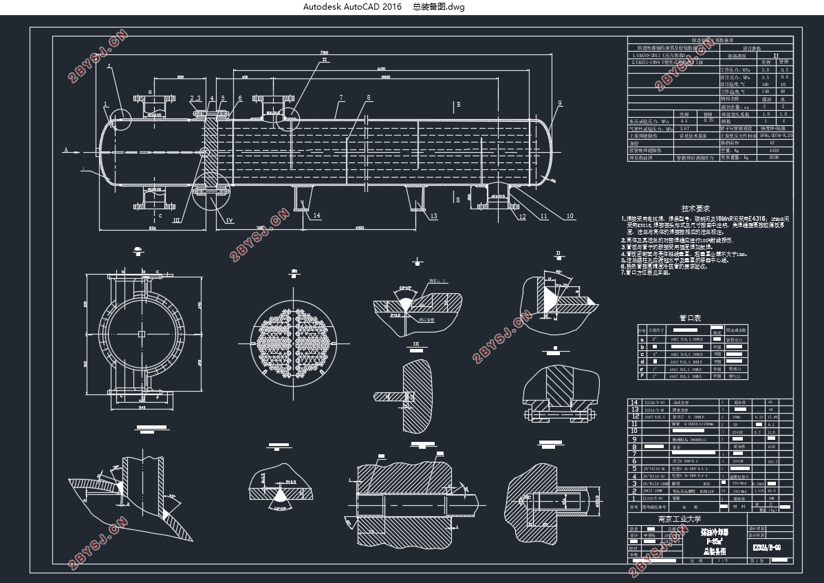
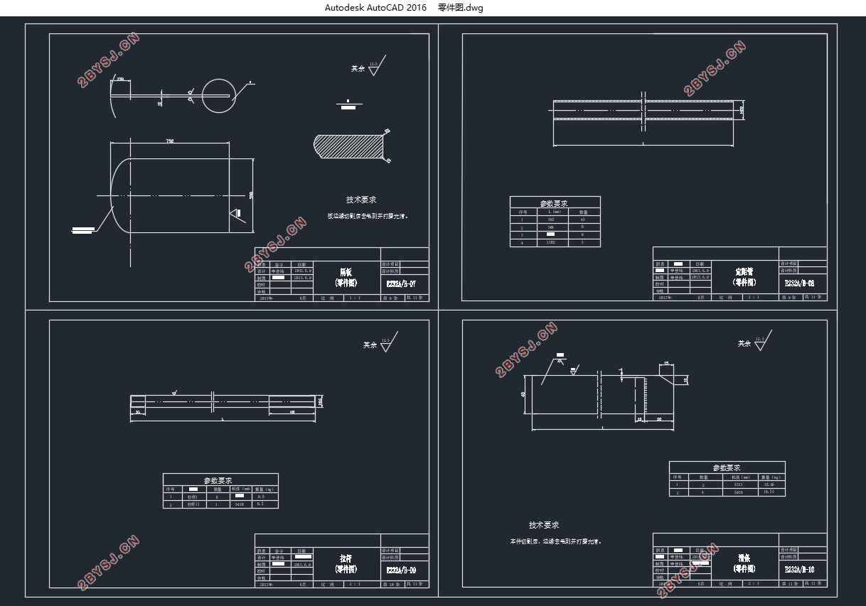
煤油冷却器的设计(含CAD零件图装配图)(论文说明书7000字,CAD图6张)
摘 要
本设计的煤油冷却器采用U形管式换热器,它在煤油的温度降到工艺所要求的温度扮演了重要角色。因水易结垢,为了便于清洗,所以水走管程,煤油走壳程。
本设计按照工艺要求所给的参数作为原始数据,通过设计计算、结构设计和其他一些计算从而初步完成满足工艺要求的装置的设计。然后进行强度校核,遵从的规范有GB151-1999《管壳式换热器》,GB150-2011《压力容器》等。最后利用SW6-2011V1.0中的U形管换热器进行强度校核。本设备制造、试验和验收是按照GB151-1999《管壳式换热器》中的II级进行,并接受劳动部颁发《压力容器安全技术监察规程》的监督。
关键词:U形管 煤油 冷却器
The design of the kerosene cooler
Abstract
This design is about kerosene cooler, it adopts the u-tube heat exchanger. It plays an important role in the transform process of kerosene industry by which the temperature of. Because water is easy to scale, and in order to clean it easily, water flow in tube side, and kerosene flow in shell side.
The parameters of technological requirement are used as raw data in this design, through the design calculation, structure design and some other calculations to preliminary finish the design that meet the technical requirements. Then the intensity should be checked, and it should examined by GB151-1999 “shell and tube heat exchanger ”, GB150-2011 “pressure vessel” and so on by hand. Finally we should use the u-tube heat exchanger of SW6-2011 v1.0 to check the intensity. The manufacture, test and check and accept of this equipment should according to GB151-1999 “shell and tube heat exchanger” class II, and should be supervised by the “pressure vessels safety technology supervision regulation supervision” that the labor department awarded.
Keywords: U tube; kerosene ; cooler
生产条件的确定
设计一个U形管式煤油冷却器,要能满足每年8.8万吨煤油冷却的任务。温度参数是:煤油进口温度140℃,出口温度40℃;循环冷却水进口温度25℃,出口温度40℃。时间参数是:每年按330天计,每天24小时连续进行。
3.1确定设计方案
3.1.1选择换热器类型
因为煤油进口温度为140℃,冷却水的进口温度为25℃,这两种流体有较大温差,并且这两种流体有且只有循环冷却水易结垢,所以选择使用U形管冷却器合适 。
3.2.2 流动空间及流速的确定
因为水易结垢,且实际生产中,冷却水一般采用循环水,更易结垢,所以使循环冷却水走管程,以便于清洗。煤油则走壳程。选用φ25×2.5的碳钢管,管内流速设为ui=0.5m/s。


目 录
摘要………………………………………………………………………I
ABSTRACT……………………………………………………………II
第一章 前言……………………………………………………………1
第二章 生产条件的确定……………………………………………3
第三章 换热器的设计计算…………………………………………4
3.1确立设计方案……………………………………………………4
3.2确定物性数据……………………………………………………4
3.3计算总传热系数…………………………………………………5
3.4计算传热面积……………………………………………………5
3.5工艺结构尺寸……………………………………………………6
3.6换热器核算………………………………………………………8
第四章 结构设计……………………………………………………13
4.1筒体……………………………………………………………13
4.2封头……………………………………………………………14
4.3接管……………………………………………………………15
4.4换热管…………………………………………………………17
4.5折流板…………………………………………………………17
4.6拉杆……………………………………………………………17
4.7支座……………………………………………………………18
第五章 设计一览表…………………………………………………19
第六章 设计结果与说明…………………………………………20
6.1设计结果讨论…………………………………………………20
6.2设计结果说明…………………………………………………20
第七章 结束语 ……………………………………………………22
第八章 参考文献……………………………………………………23
