
推动架工艺及夹具设计(含CAD零件图装配图)
无需注册登录,支付后按照提示操作即可获取该资料.
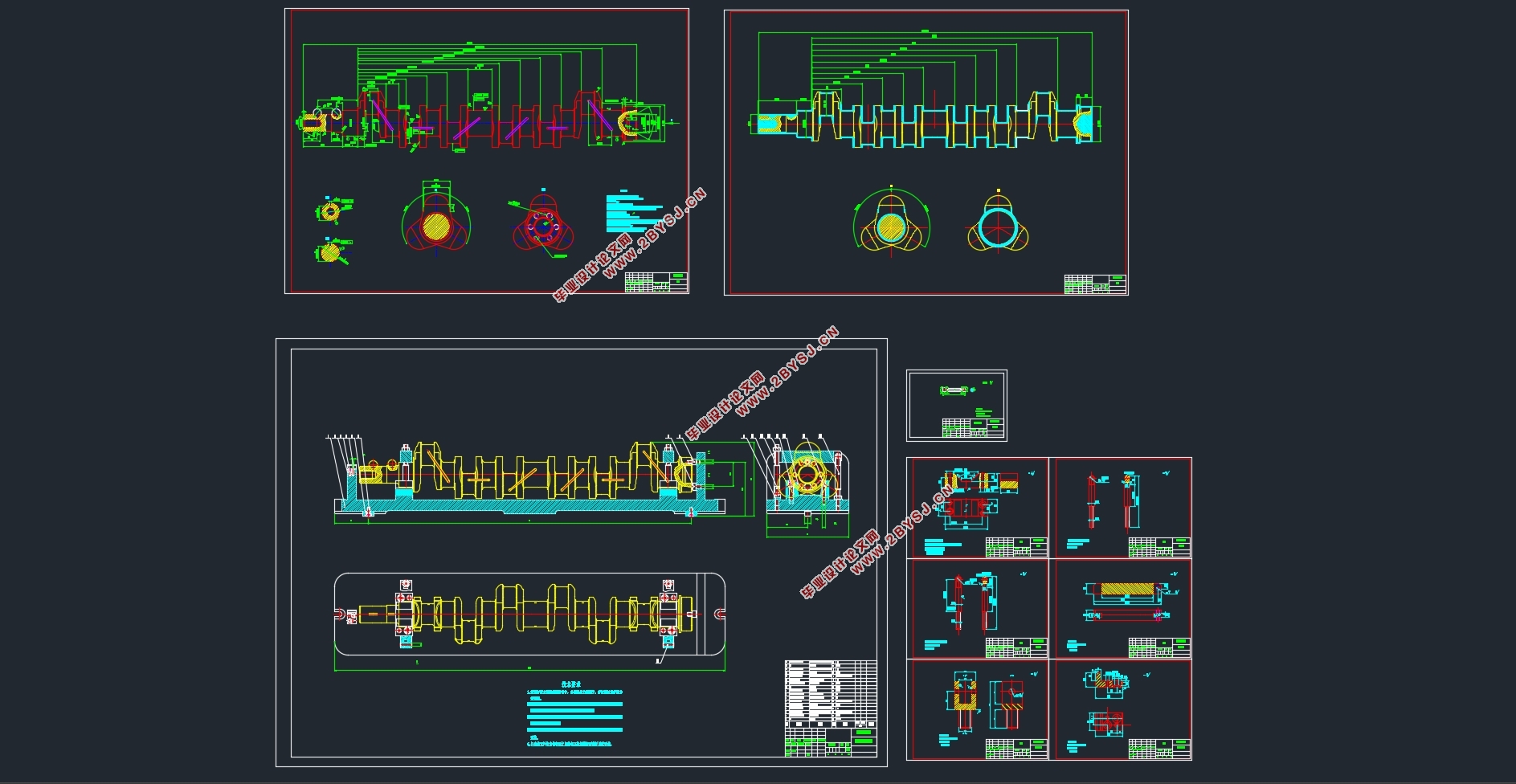
推动架工艺及夹具设计(含CAD零件图装配图)(论文说明书25000字,外文翻译,CAD图7张)
摘 要
本文是在推动架的图样分析后进行推动架的机械加工工艺路线的设计,同时按照其中的加工工序的要求设计夹具。
推动架的主要加工内容是表面和孔。其加工路线长,加工时间多,加工成本高,零件的加工精度要求也高。按照机械加工工艺要求,遵循先面后孔的原则,并将孔与平面的加工明确划分成粗加工和精加工阶段以保证加工精度。基准选择以底面作为粗基准,以底面与两个工艺孔作为精基准,确定了其加工的工艺路线和加工中所需要的各种工艺参数。
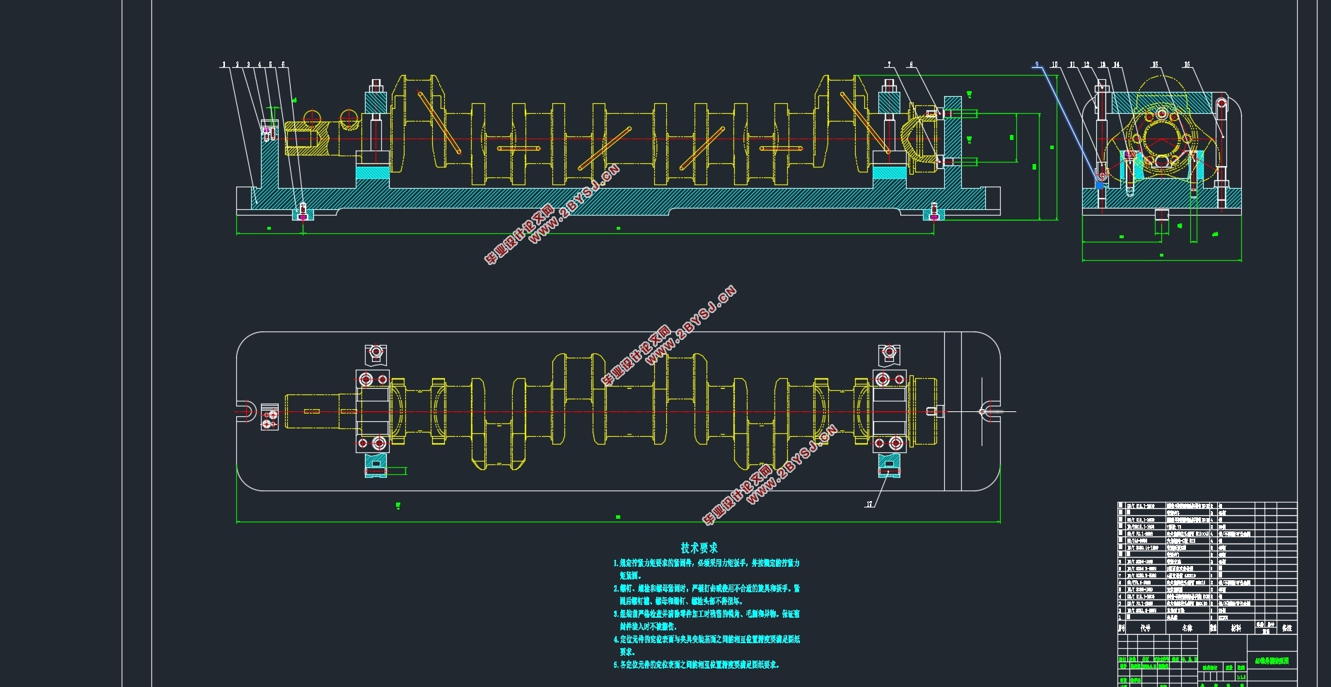
在零件的夹具设计中,主要是根据零件加工工序要求,分析应限的自由度数,进而根据零件的表面特征选定定位元件,再分析所选定位元件能否限定应限自由度。确定了定位元件后还需要选择夹紧元件,最后就是确定专用夹具的结构形式。
加工技术是随着机床的生产和发展而逐步完善的一种应用技术。加工过程是通过机床上的刀具直接改变形状、大小、表面位置和表面状态,使其成为成品或半成品的过程。 适用于现代批量加工工件的方法。由于社会生产力不断的解放和科学技术的发展,加工技术也在不断的创新,推出别具一格的加工方法,间接推动国家的发展。如何快速应对瞬息万变的市场需求。在零件加工生产线的设计和规划中,满足大中型、高效率、低成本生产的需要是一个重要的考虑因素。机床加工的柔性生产线的高速切削技术已成为大批量加工的发展方向。本文的主题是推动架零件的工艺工装设计。
在推动架加工过程中,设计机械零件的加工工艺规划。其主要内容包括部件产品的结构特点、形状尺寸和技术要求等,分析其零件的作用等,在这基础上,确定毛坯的类型,绘制毛坯图。进行基面的选择,确定加工过程中的粗基准和精基准。根据选好的基准,制订工艺路线。分析并优化零件的加工路线。 合理的选择刀具、机床、量具等加工设备,计算在加工过程的理论上的切削参数、基本工时。关键是决定出各个工序的工艺装备及切削用量。最后设计零件的专用夹具,分析其定位误差、切削力、夹紧力等参数,计算此夹具是否成立。难度是在设计过程中,合理的选择数据。加深理解和掌握加工工艺,切削加工的知识与实践结合起来,实现毕业设计的学习和提高自我的专业素质。
关键词:推动架;加工工艺;工序;专用夹具
Driving Frame Technology and Fixture Design
Abstract
In this paper, after the pattern analysis of the push frame, the design of the mechanical processing process of the push frame is carried out, and the fixture is designed according to the requirements of the processing process.The main processing content of the push frame is surface and hole. Its processing route is long, processing time, processing cost is high, parts processing accuracy requirements are also high. In accordance with the requirements of mechanical processing technology, the principle of "first surface, then hole" is followed, and the processing of hole and plane is clearly divided into rough processing and finishing stages to ensure the processing accuracy. The base plane is chosen as the rough base plane, and the base plane and two process holes are used as the fine datum.In the fixture design of parts, it is mainly based on the requirements of parts processing process, analysis of the limited degree of freedom, and then according to the surface characteristics of parts to select positioning elements, and then analyze the selected position elements can limit the degree of freedom. After determining the positioning element, it is necessary to select the clamping element, and finally determine the structure of the special fixture.Processing technology is a kind of application technology which is gradually improved with the production and development of machine tools. Machining process is the process of changing the shape, size, surface position and surface state of the cutting tool directly on the machine tool to make it into finished or semi-finished products. Suitable for modern batch machining workpiece method. Due to the continuous liberation of social productive forces and the development of science and technology, processing technology is also in constant innovation, innovative achievements unique processing methods, indirectly promote the development of the country. How to quickly respond to the ever-changing market demand. In the design and planning of spare parts production line, it is an important consideration to meet the needs of large and medium-sized, high-efficiency and low-cost production. The high speed cutting technology of flexible production line has become the development direction of mass machining. The theme of this paper is to promote the design of the frame parts process tooling.Design the machining process planning of mechanical parts in the process of pushing frame. Its main content includes the structural characteristics of components, shape and size and technical requirements, etc., analysis of the role of its parts, etc., on this basis, determine the type of blank, draw blank diagram. Base plane selection is carried out to determine the coarse and fine datum in the processing process. According to the selected benchmark, formulate the process line. Analyze and optimize the machining route of parts. Reasonable selection of cutting tools, machine tools, measuring tools and other processing equipment, calculation of the theoretical cutting parameters in the processing process, the basic working hours. The key is to determine the process equipment and cutting parameters of each process. Finally, the special fixture of the parts is designed, and its positioning error, cutting force, clamping force and other parameters are analyzed to calculate whether the fixture is valid. The difficulty is in the design process, the reasonable choice of data. Deepen understanding and master the processing technology, cutting knowledge and practice together, to achieve the graduation design learning and improve my professional quality.
Key words: Push frame processx; processing technology; process; special fixture
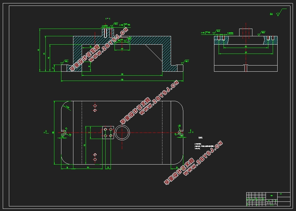
2.2 推动架的图样分析
在编制推动架机械加工工艺规程之前,首先应研究推动架的工作图样和产品装备图样,熟悉该产品的用途、性能及工作条件,明确该推动架在产品中的位置和作用;了解并研究各项技术条件制定的依据,找出其主要技术要求和技术关键,以便在拟定工艺规程时采用适当的措施加以保证。
推动架的材料为HT200,灰铸铁生产工艺简单,铸造性能优良,减震性能良好。传动推动架需要加工表面以及加工表面的位置要求。现分析如下:
1)该零件为机床推动架,主要加工部位为平面和孔系,其结构复杂,精度要求又高,加工时应注意选择定位基准及夹紧力。
2)材料HT200。
3)铸件人工时效处理。
2.3 工艺分析
在编制零件机械加工工艺规程前,首先应研究零件的工作图样和产品装配图样,熟悉该产品的用途、性能及工作条件,明确该零件在产品中的位置和作用;了解并研究各项技术条件制订的依据,找出其主要技术要求和技术关键,以便在拟订工艺规程时采用适当的措施加以保证。
工艺分析的目的:一是审查零件的结构形状及尺寸精度、相互位置精度、表面粗糙度、材料及热处理等的技术要求是否合理,是否便于加工和装配;二是通过工艺分析,对零件的工艺要求有进一步的了解,以便制订出合理的工艺规程。
经审查,此零件图的尺寸公差、粗糙度等完善,表达清楚。
1)机器零部件是为整机工作性能服务的,零部件结构工艺性应服从整机的工艺性。
2)在满足工作性能的前提下,零件造型应尽量简单,同时应尽量减少零件的加工表面数量和加工面积;尽量采用标准件、通用件和外购件;增加相同形状和相同元素(如直径、圆角半径、配合、螺纹、键、齿轮模数等)的数量。
3)零件设计时在保证零件使用功能和充分考虑加工可能性、方便性、精确性的前提下应符合经济性要求,即应尽量降低零件的技术要求(加工精度和表面质量),以使零件便于制造。
4)尽量减少零件的机械加工余量,力求实现少或无切屑加工,以降低零件的生产成本。合理选择零件材料,使其机械性能适应零件的工作条件,且成本较低。
5)符合环境保护要求,使零件制造和使用过程中无污染、省能源,便于报废、回收和再利用。

目 录
摘 要 i
Abstract iii
1 绪论 1
1.1 本课题的研究内容和意义 1
1.2 国内外的发展概况 1
1.3 本课题应达到的要求 2
2 推动架的图样分析 4
2.1 推动架的作用 4
2.2 推动架的图样分析 4
2.3 工艺分析 5
3 工艺规程设计 7
3.1 确定毛坯的制造形式 7
3.2 定位基准的选择 9
3.2.1 粗基准的选择 10
3.2.2 精基准的选择 11
3.3 切削液的选择 11
3.4 检验工件过程 12
3.5 废品的出现原因 13
3.6 质量超差的解决方法 13
3.7 拟定工艺路线 14
3.7.1 划分加工阶段 14
3.7.2 工序集中与分散 14
3.7.3 安排加工顺序 16
3.7.4 拟定加工工艺路线 17
3.8 机械加工余量、工序尺寸及毛坯尺寸的确定 18
3.9 量具的选择 20
3.10 刀具的选择 21
3.11 确定切削参数 21
4 推动架钻孔夹具设计 41
4.1 研究原始质料 41
4.2 定位、夹紧方案的选择 41
4.3 零件图的设计 42
4.4 钻床装配图确定 45
4.5 夹紧装置 46
4.6 切削力及夹紧力的计算 47
4.7 误差分析与计算 49
4.8 夹具设计及操作的简要说明 50
结 论 51
参考文献 53
外文资料 54
致 谢 62