皮带轮的冲压工艺及模具设计(含CAD图)
无需注册登录,支付后按照提示操作即可获取该资料.
皮带轮的冲压工艺及模具设计(含CAD图)(任务书,开题报告,外文翻译,论文说明书9000字,CAD图8张)
摘要
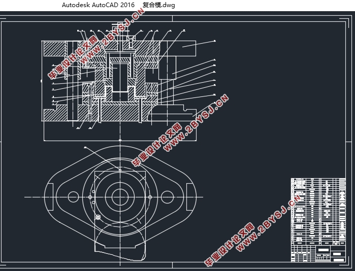
随着模具行业的不断发展,模具的加工制造水平逐渐成为衡量各国工业水平高低的标准,本文便是对皮带轮的工艺分析和模具设计,首先根据零件的批量使用要求,结构,及材料对零件进行工艺性能分析,通过零件计算出毛坯的尺寸,然后计算出所需的拉深次数,然后分析冲孔的顺序,拟定出了四种工艺方案,最后确定为正反拉深复合模,加上单工序冲孔模。对零件进行合理的排样,从而达到最大的材料利用率,计算出落料力,卸料力,拉深力等冲压工艺力,选择合适的压力机吨位,计算出落料部分,正反拉深部分,冲孔部分的刃口尺寸。确定合理的模具闭合高度,然后设计出各个模具的外形尺寸,并进行校核。然后设计,查表得出各个零件的外形尺寸,完成零件图与装配图的绘制。
关键词:拉深,正反拉深,复合模,模具设计
Abstract
With the continuous development of mold industry, the level of manufacturing mold gradually become the standard that measure the level of national industry. This article is aimed at analyzing the craft and designing the mold of pulley. Firstly, according to the requirements of the batch, structures, materials of parts, analyzing theprocess performance of parts. Calculate the size of blank with the part, then calculate the times of drawing .Analyzing the order of punching, protocol four kinds of scheme. Finally, determine to adopt the pro and con drawingsuperposable die, and single punching die. The reasonable layout of parts could get the maximum utilization of material. Calculate the blanking force, unloading force ,drawing force and other stamping process force. Select the appropriate tonnage of press. Calculate the edge sizes of blanking parts, pro and con drawing parts and punching parts. Select the seasonable shut height of mold. Design the dimension of all molds, and check it. Look-up table and get the dimension of components. Finish the drawing of components drawing and assembly drawing.
Keys:drawing, pro and con drawing, superposable die , mold design
零件的工艺性能分析是指对零件进行冲压加工时的难易程度,而这取决于零件的外形尺寸,结构,和材料。
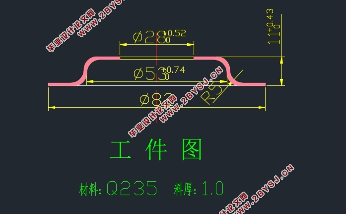
首先进行零件的加工工艺性能分析:该零件为皮带轮,采用的材料为08F钢,强度低,但是韧性和塑性较好,易于拉深。零件中尺寸有∅〖100〗_(-0.2)^0,∅〖50〗_(-0.018)^(+0.07),和18(_-^+)0.1。其余没有标注的公差可以按自由公差进行计算。零件外形尺寸为∅110,为中小型零件。零件的厚度为2mm。
然后对零件的结构工艺性能进行分析:首先零件整体为带凸缘的圆筒形件所以肯定需要拉深来成型,然后圆筒底部也有个内凹的圆孔,所以需要与前面拉深方向相反的拉深过程,最后由于筒底部中间有个圆孔,所以需要冲孔,总的工艺步骤有落料,拉深(一次或多次),反拉深(一次或多次),最后为冲孔。所以可以提出很多不同的工艺方案。


目录
摘要 I
Abstract II
第1章绪论 1
第2章分析零件的工艺性 2
第3章确定工艺方案 3
3. 1计算毛坯尺寸 3
3. 2拉深次数的确定 4
3.2.1正拉深的拉深次数 4
3.2.2反拉深的拉深次数 4
3. 3确定工艺方案 5
第4章主要的工艺参数的计算 6
4. 1确定排样方案,计算材料利用率 6
4. 2计算工艺力,初选压力机 6
4.2.1落料过程 6
4.2.2正拉深过程 6
4.2.3反拉深过程 7
4.2.4拉深功的计算 7
4.2.5冲孔力的计算 8
4.2.6初选复合模压力机 8
4.2.7初选冲孔模压力机 8
第5章模具的结构设计及刃口尺寸 9
5. 1模具结构形式 9
5. 2落料正反拉深复合模 9
5.2.1落料 9
5.2.2正拉深 10
5.2.3反拉深 11
5. 3冲孔模 11
第6章主要零件结构设计 12
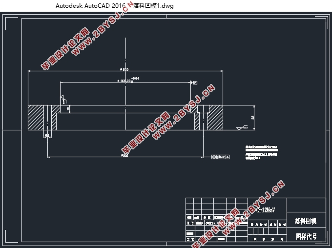
6. 1落料凹模的设计 12
6. 2落料凸模(正拉深凹模)的设计 12
6. 3凸凹模 13
6. 4反拉深凸模 14
6. 5冲孔的凹模 15
6. 6冲孔凸模 15
6. 7冲孔模弹簧设计 16
第7章模架的选用及闭合高度的校核 17
7. 1复合模的模架选用 17
7. 2复合模闭合高度的校核 17
7. 3复合模的压力中心确定 17
7. 4冲孔模的模架选用 17
7. 5冲孔模闭合高度的校核 18
7.6冲孔模的压力中心 18
第8章模具装配图 19
8. 1落料正反拉深复合模总装图 19
第9章选定压力机 20
9.1复合模压力机 21
9.2冲孔模压力机 21
第10章模具的DYNAFORM模拟 22
10. 1DYNAFORM简介 22
10. 2拉深模的模拟 22
10.2.1前处理部分 22
10.2.2后处理部分 24
第11章总结 25
参考文献 26
致谢 27
