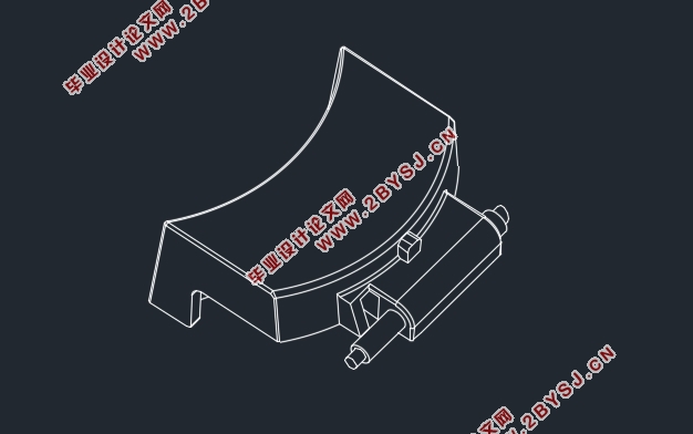
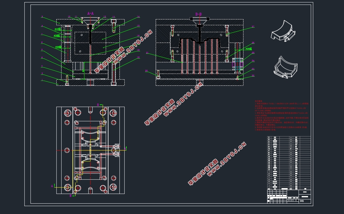
汽车塑料扣手成型工艺分析与模具设计(含CAD零件图装配图)
无需注册登录,支付后按照提示操作即可获取该资料.
汽车塑料扣手成型工艺分析与模具设计(含CAD零件图装配图)(任务书,开题报告,外文翻译,论文说明书11000字,CAD图9张)
摘要
本次的毕业设计内容是汽车塑料扣手成型工艺分析及模具设计。采用了Moldflow软件对塑料扣手进行了模流分析,在不同位置设置浇口、模具温度、注射速率等,分析了保压时间、熔接痕、顶出时的体积收缩率、气穴分布,确定了最佳浇口位置以及优化了熔体温度、模具温度、注射压力等工艺参数。在此基础上确定了最终成型方案,设计并计算了相关成型零部件,然后利用UG软件的注塑模向导模块设计了汽车塑料扣手的三维注塑模具。
利用Moldflow软件,可以在设计模具前进行模流分析,能有效减少缺陷,提高塑件的质量,显著提高了注塑模具设计的效率。
关键词:塑料扣手,模流分析;工艺参数;模具设计
ABSTRACT
The contents of this graduation design is the molding process analysis and die design of car plastic handle. Use the Moldflow software to make the mold flow analysis of plastic handle, by setting different gate location, melt temperature, mold temperature, injection rate, volume shrinkage of the holding time, weld line, ejection rate, cavitation, to determine the optimal gate location and optimizing the process parameters, melt temperature mold temperature, injection pressure etc.. On this basis, the final forming scheme is determined, the data of the relevant forming parts are designed and calculated, and then the UG software is used to design the three - dimensional injection mold of the car plastic handle.
Using Moldflow software,mold flow analysis can be carried out before the die
design, which can effectively reduce the injection defects, improve the quality of plastic parts, and significantly improve the efficiency of injection mold design.
Key Word: plastic handle;mold flow analysis;process parameters;mould design


目 录
第1章 绪论 1
1.1 引言 1
1.2 模具CAD/CAM 1
1.3 研究的主要内容 1
第2章 基于Moldflow软件的模流分析 2
2.1有限元模型的建立 2
2.1.1 Moldflow 2
2.1.2 零件三维模型的建立 2
2.1.3 有限元模型的导入 2
2.2 网格的建立与修复 3
2.3 浇口的选择 6
2.3.1 浇口匹配性分析 6
2.3.2 浇口的位置选择 6
2.3.3 型腔数目的确定 9
2.4 注塑工艺参数的优化 9
2.4.1 熔体温度的优化选择 9
2.4.2 模具温度的优化选择 11
2.4.3 注射速率的优化选择 12
2.4.4 保压压力的优化选择 14
2.4.5充填时间的确定 17
2.5 本章小结 17
第3章 塑料扣手注射成型模具设计及计算 18
3.1 零件分析 18
3.1.1 塑料的工艺分析 18
3.1.2 塑件的材料分析 19
3.2 注射设备的选择 20
3.2.1塑件和流道体积的计算 20
3.2.1锁模力的计算 20
3.3 标准模架的选择 21
3.4 成型零部件的设计 21
3.4.1 分型面的确定 21
3.4.2 成型零部件工艺尺寸的计算 22
3.5 浇注系统的设计 25
3.7.1 脱模力的计算 26
3.5.2 分流道的设计 26
3.5.3 浇口的设计 26
3.5.4 排气系统 27
3.6 导向机构的设计 28
3.7 脱模机构的设计 28
3.7.1 脱模力的计算 28
3.7.2 推杆的设计 29
3.8 冷却系统的设计 30
3.8.1 冷却水管设计的要点 30
4.8.1 冷却水管的设计 30
3.9 模具装配图及零件图 31
第4章 设计总结 37
参考文献 38
致谢 40
