车床变速箱中拔叉及专用夹具设计(含CAD毛坯图夹具图)
无需注册登录,支付后按照提示操作即可获取该资料.
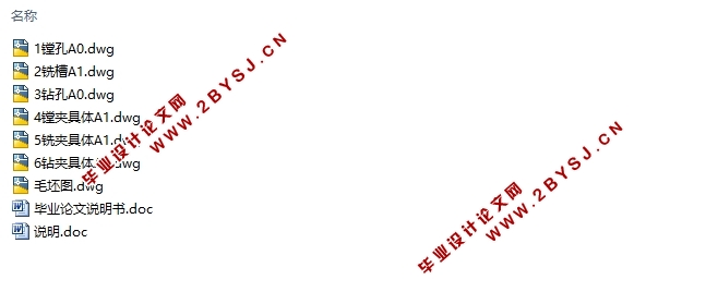
车床变速箱中拔叉及专用夹具设计(含CAD毛坯图夹具图)(论文说明书11000字,CAD图纸7张)
摘 要
本次设计是车床变速箱中拔叉零件的加工工艺规程及一些工序的专用夹具设计。此拔叉零件的结构较为复杂,其加工的地方主要是孔和平面。本设计先加工孔后加工面。将孔与平面的加工明确划分成粗加工和精加工阶段以保证它们的加工精度。基准选择以拔叉右面的最大的平面作为粗基准,来加工中间的通孔,然后以此加工过的孔作为精基准。主要加工工序安排是先以中心孔定位加工出顶平面和右侧平面以及下面的大孔的两平面,再以中心孔定位加工出下端的大孔。加工时是用镗床镗孔。最后以这两个孔为基准,分别加工右侧的槽和顶面的螺纹底孔。整个加工过程选用了钻床、铣床和镗床。工件在机床上定位夹紧选用专用夹具,夹紧方式为手动夹紧,夹紧可靠,操作方便。因此生产效率较高,适用于大批量、流水线上加工,能够满足设计要求。
关键词:加工工艺,定位,夹紧,专用夹具
Abstract
This design is a lather to become soon an appropriation for inside pulling out fork spare parts processing craft rules distance and some work prefaces tongs design.This pull out the construction of the fork spare parts than for complicacy, its the place that process is a peaceful in bore primarily.This design processes after processing first the bore.Process with flat surface the clear and definite dividing the line the bore the coarseness processes to process with the nicety the stage to guarantee their process the precise degree.The basis choice to pull out rough basis of conduct and actions of the biggest flat surface of the right in fork, process the in the center in general use bore, then be used as the precise basis with the bore that processed.Processing primarily work preface arrangement is first to process a flat surface with the center bore fixed position with the right side flat surface and below big bore of two flat surface, again with center bore the fixed position processes the big bore that carry down.While processing is to use the boring machine boring bore.Regard these two bores as the basis finally, process the right-hand slot respectively with the thread bottom bore of the a.Whole processes the process chose to use to the drill machine, miller with the boring machine .The tongs chooses to use the appropriation tongs, clipping tight way as to move to clip tight, clip tight and dependable, operation convenience.Therefore produce the efficiency higher, be applicable to the large quantity measures, the flowing water is on-line to process.Can satisfy the design request.
Key words: Process the craft,Fixed position,Clip tight,Appropriation tongs
2.1零件的分析
2.1.1零件的作用
题目所给的零件是CA6140车床的拨叉。它位于车床变速机构中,主要起换档,使主轴回转运动按照工作者的要求工作,获得所需的速度和扭矩的作用。
2.1.2零件的工艺分析
零件的材料为HT200,灰铸铁属于脆性材料,故不能锻造和冲压。但灰铸铁的铸造性能和切削加工性能优良。以下是拨叉需要加工的表面以及加工表面之间的位置要求:
(1) 中心圆孔Ф 。
(2) 的螺纹孔垂直于中心孔,其中心与右面的距离为 。
(3) 键槽 与中心孔有0.08的垂直度,深为 。
(4) 半孔 与中心孔有 的位置关系,其宽为 与中心孔有0.1的垂直度。
由上面分析可知,可以先加工拨叉中心孔,然后以此作为基准采用专用夹具进行加工,并且保证位置精度要求。再根据各加工方法的经济精度及机床所能达到的位置精度,并且此拨叉零件没有复杂的加工曲面,所以根据上述技术要求采用常规的加工工艺均可保证。
目 录
第一章 绪论 1
1.1课题背景 1
1.2夹具的发展史 1
1.3小结 1
第二章 拨叉80-08的加工工艺规程设计 3
2.1零件的分析 3
2.1.1零件的作用 3
2.1.2零件的工艺分析 3
2.2确定生产类型 3
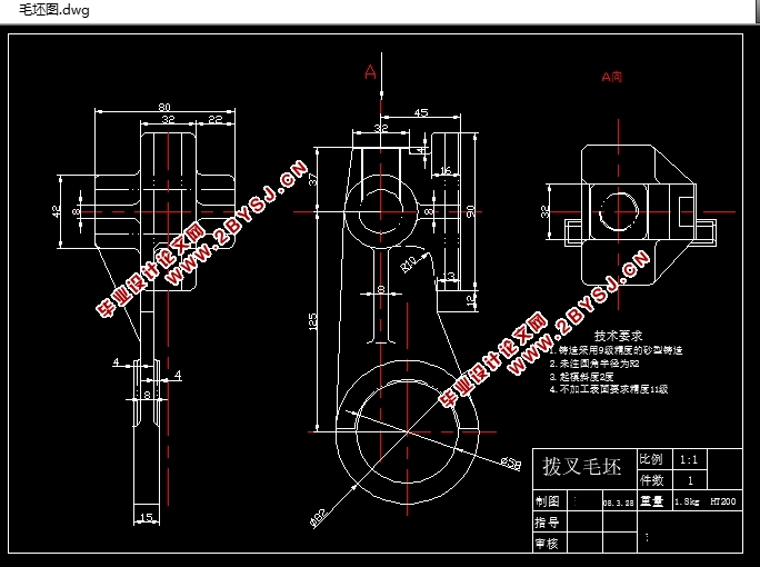
2.3确定毛坯 3
2.3.1确定毛坯种类 3
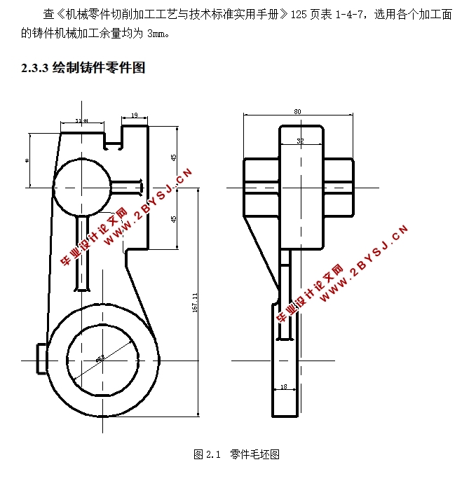
2.3.2确定铸件加工余量及形状 4
2.3.3绘制铸件零件图 4
2.4工艺规程设计 4
2.4.1选择定位基准 4
2.4.2制定工艺路线 5
2.4.3选择加工设备和工艺设备 6
2.4.4机械加工余量、工序尺寸及公差的确定 7
2.5确定切削用量及基本工时 8
2.5.1工序1:粗铣Φ25H7的两侧面 8
2.5.3工序3:钻Φ25H7的通孔 9
2.5.4工序4:扩Φ25H7的通孔 11
2.5.5工序5:铰Φ25H7的通孔 11
2.5.6工序6:粗铣a、b面 12
2.5.7工序7:粗铣Φ60H12孔的两面 13
2.5.8工序8:精铣Φ60H12孔的两面 14
2.5.9工序9:粗镗下端Φ60H12的孔 15
2.5.10工序10:半精镗下端孔到Φ60H12 15
2.5.11工序11:粗铣16H11的槽 16
2.5.12工序12:半精铣16H11的槽 17
2.5.13工序13:钻Φ20.50的孔 17
2.5.14工序14:攻M22×1.5的螺纹 19
2.5.15工序15:铣开Φ60H12的孔 19
2.6本章小结 20
第三章 专用夹具设计 21
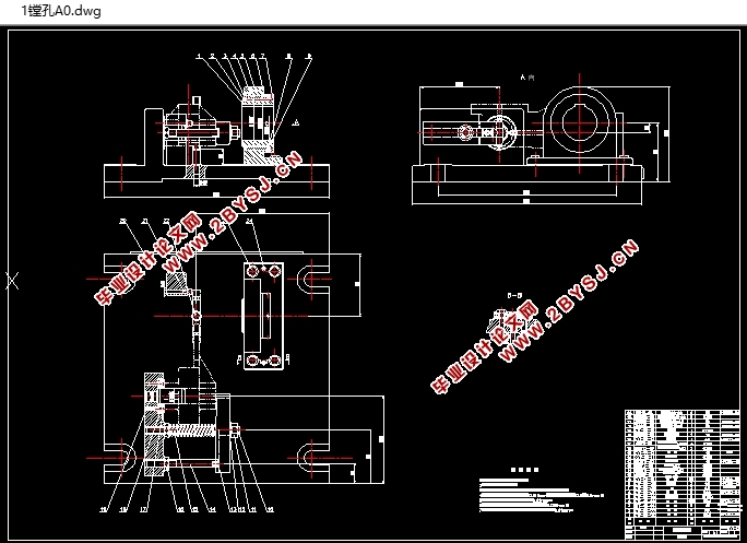
3.1镗孔夹具设计 21
3.1.1问题的提出 21
3.1.2夹具的设计 21
3.2铣槽夹具设计 24
3.2.1问题的提出 24
3.2.2夹具的设计 24
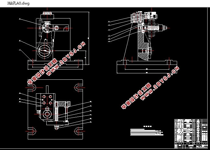
3.3钻孔夹具设计 28
3.3.1问题的提出 28
3.3.2夹具的设计 29
3.4本章小结 34
第四章 结论 35
参 考 文 献 36
致谢 37
