
大型数控套筒回转式尾座(含CAD零件图装配图)
无需注册登录,支付后按照提示操作即可获取该资料.
大型数控套筒回转式尾座(含CAD零件图装配图)(论文说明书6800字,外文翻译,CAD图8张)
摘 要
本文主要目的是进行大型数控套筒回转式尾座的设计。大型数控套筒回转式尾座具有芯轴随工件回转、压力表显示压力、手动换档齿轮变速的功能。本文设计并介绍尾座的大致工作方式,手动换挡齿轮变速的安装过程以及对尾座的受力情况进行分析和强度及稳定性的校核。对普通圆柱蜗杆传动承载能力的计算包括蜗杆传动的受力分析,蜗轮齿面接触疲劳强度计算,蜗轮齿根弯曲疲劳强度计算,蜗杆的刚度计算以及蜗杆传动的精度等级的选择;直齿锥齿轮传动的强度计算包括轮齿的受力分析,对齿根弯曲疲劳强度计算以及按照齿面接触疲劳强度计算;轴的计算包括轴的强度校核计算和轴的刚度校核计算。分析设计过程,并作出总结和改进方式。根据设计方案,利用cad绘制总装配图以及部分主要零件图,利用solidworks软件绘制尾座结构。
关键词:尾座;手动换挡;机械设计
Abstract
The main purpose of this paper is to design a large numerical control sleeve rotary tailstock. Large numerical control sleeve rotary tailstock has the function of rotating the core shaft with the workpiece, the pressure gauge shows pressure, and the gear shifting gear which is changed manually. This paper designs and introduces the general working mode of the tail seat, the installation process of the gear shift gear shift, and the analysis and the strength and stability of the rear seat. Ordinary cylindrical worm drive bearing capacity calculation including the worm drive force analysis, the worm gear tooth surface contact fatigue strength calculation, the worm gear tooth root bending fatigue strength calculation, the calculation of the rigidity for the worm and worm drive the accuracy grade of choice. The strength calculation of the bevel gear transmission includes the force analysis of the gear teeth, the calculation of the fatigue strength of the tooth root and the fatigue strength of the tooth surface. The calculation of the shaft includes the strength of the shaft and the calculation of the rigidity of the shaft. Analyzing design process and making summary and improvement. According to the design scheme, the general assembly drawing and some main parts drawings are drawn by CAD, and the tail-seat structure is drawn with Solidworks software.
Key Words:The tailstock; Manual shift; Mechanical design

目录
摘 要 I
Abstract II
1 绪 论 - 1 -
1.1课题研究的目的与意义 - 1 -
1.2相关课题国内外发展的现状及发展趋势 - 1 -
2 总体方案 - 3 -
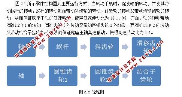
2.1工作方式 - 3 -
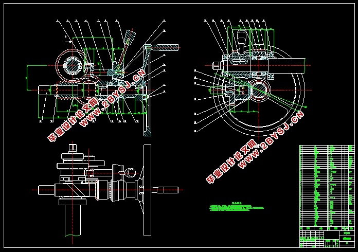
2.2 手动换挡齿轮变速的安装过程 - 4 -
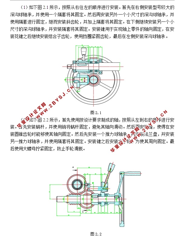
2.2.1 安装步骤 - 4 -
2.2.2 注意事项 - 4 -
2.3 具体装配过程 - 4 -
3 尾座的受力情况分析 - 5 -
3.1 普通圆柱蜗杆传动承载能力计算 - 5 -
3.1.1 蜗杆传动的受力分析 - 5 -
3.1.2 蜗轮齿面接触疲劳强度计算 - 6 -
3.1.3 蜗轮齿根弯曲疲劳强度计算 - 6 -
3.1.4 蜗杆的刚度计算 - 6 -
3.1.5 蜗杆传动的精度等级的选择 - 7 -
4 直齿锥齿轮传动的强度计算 - 7 -
4.1直齿锥齿轮传动的强度计算 - 7 -
4.1.1 设计参数 - 7 -
4.1.2轮齿的受力分析 - 7 -
4.1.3 按齿根弯曲疲劳强度计算 - 8 -
4.1.4 按齿面接触疲劳强度计算 - 10 -
5 轴的计算 - 12 -
5.1 轴的强度校核计算 - 12 -
5.2 轴的刚度校核计算 - 13 -
5.2.1 轴的扭矩刚度校核计算 - 13 -
6设计并绘制总装图及部分零件图 - 14 -
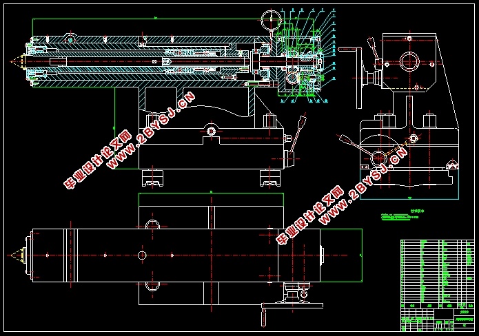
6.1尾座的零件图 - 14 -
6.2 尾座的装配图 - 15 -
7 结论 - 17 -
参考文献 - 18 -
附录 Ⅰ外文翻译 - 19 -