
大型客车悬架系统的设计(含CAD零件装配图)
无需注册登录,支付后按照提示操作即可获取该资料.
大型客车悬架系统的设计(含CAD零件装配图)(任务书,开题报告,外文翻译,论文说明书12000字,CAD图纸6张,答辩PPT)
Design of Large Bus Suspension System
摘 要
车辆有较低的固有频率时,行驶平顺性好,乘坐舒适,车辆使用寿命长,同时减轻车辆对路面的破坏。空气悬架的运用可大大降低车辆固有频率,所以本设计采用空气悬架方案。
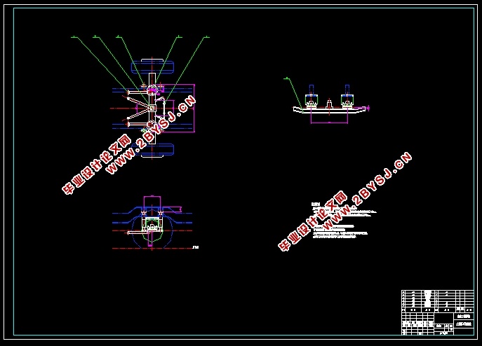
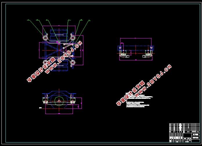
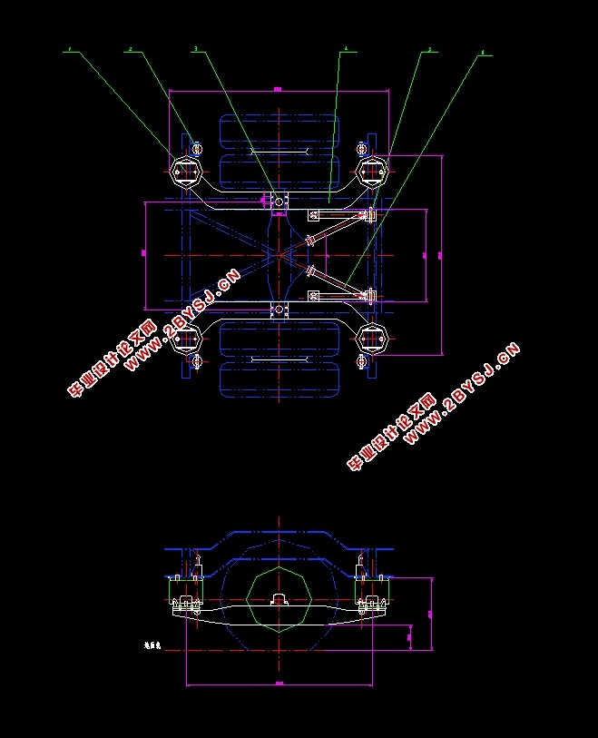
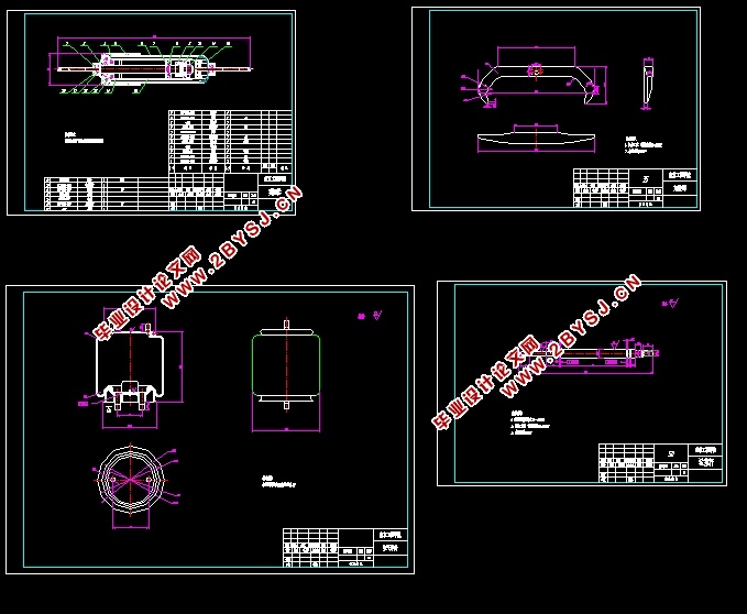
本文综述了空气悬架的发展史,组成结构和工作原理,设计了一套大型客车的空气悬架系统。总体方案为:前悬架采用四连杆非独立悬架结构,搭配两个空气弹簧分布在车身两侧,配合四支减振器和一个横向稳定杆工作。后悬架也采用四连杆非独立悬架结构,搭配四个空气弹簧固定在悬架的C型梁上,同时配合四支减振器工作。设计计算了空气弹簧,减振器横向稳定器,选择了适合的导向机构并采用CAD制图。
校核表明设计方案达到了预期的低频率,整车侧倾角也在要求范围内,较为合理。
关键词:大型客车;空气悬架;空气弹簧;设计
ABSTRACT
With lower natural frequency vehicles will be driven more comfort, a long service life will be given to the vehicle and also the damage to road from the vehicle will be reduced. The natural frequency of the vehicle can be greatly reduced when equipped with air-suspension system. With these benefits air-suspension is selected in this design program.
The development history, structures and working principle of air-suspension in this paper is reviewed. Two air springs are located in the body sides with the four-link front suspension structure of non-independent suspension work with four shock absorbers and a stabilizer bar. Four-bar linkage is also used in the rear suspension. Four air-springs that each one is supported with a shock absorber are fixed in the C-beam. Air springs shock absorbers and a horizontal stabilizer are calculated and designed in this paper, appropriate guide mechanism is selected and AUTOCAD is used for drawings, with these methods a large bus air suspension system is designed.
Checking the design program shows that the desired low-frequency has been achieved, also the vehicle roll angle is within the requirements, the whole program is reasonable.
Keywords:Large buses,Air suspension,Air spring,Design
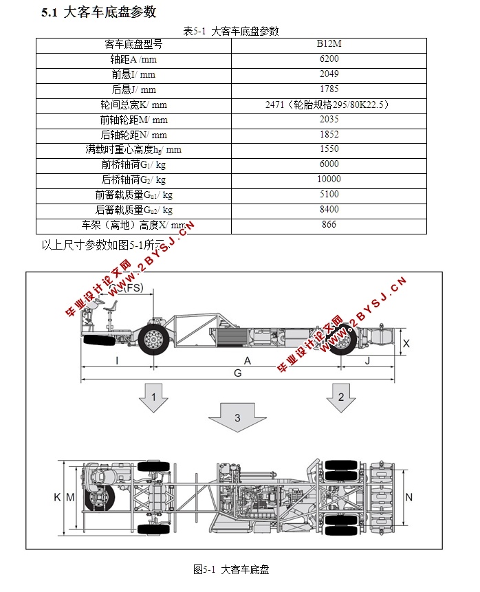
大客车底盘参数
表5-1 大客车底盘参数
客车底盘型号 B12M
轴距A /mm 6200
前悬I/ mm 2049
后悬J/ mm 1785
轮间总宽K/ mm 2471(轮胎规格295/80K22.5)
前轴轮距M/ mm 2035
后轴轮距N/ mm 1852
满载时重心高度hg/ mm 1550
前桥轴荷G1/ kg 6000
后桥轴荷G2/ kg 10000
前簧载质量Gu1/ kg 5100
后簧载质量Gu2/ kg 8400
车架(离地)高度X/ mm 866


目 录
第一章 绪论 1
1.1 空气悬架发展史 1
1.1.1国外空气悬架的发展 1
1.1.2国内空气悬架的发展 2
1.2悬架概述 2
1.2.1悬架的功能 2
1.2.2悬架的组成 3
1.2.3悬架的分类 3
第二章 空气悬架系统 5
2.1高度控制阀 5
2.2减振器 6
2.3导向机构 7
2.3.1纵向单臂式导向机构 7
2.3.2A形架导向机构 8
2.3.3四连杆式导向机构 8
2.4横向稳定杆 8
第三章 典型客车空气悬架 10
3.1 独立悬架 10
3.1.1 带球头副的虚拟主销式双横臂悬架 10
3.1.2 实体主销式双横臂悬架 10
3.1.3 错位十字轴式虚拟主销式双横臂悬架 11
3.2 非独立悬架 11
3.2.1 五连杆空气悬架 11
3.2.2 四连杆空气悬架 12
第四章 空气弹簧概述 14
4.1空气弹簧的种类 14
4.1.1膜式空气弹簧 14
4.1.2囊式空气弹簧 15
4.2空气弹簧的主要参数特点 15
第五章 空气悬架系统结构设计和计算 16
5.1底盘参数 16
5.1.1空气弹簧布置 17
5.1.2导向机构选择 17
5.2空气弹簧的计算 18
5.3减振器的计算 19
5.4横向稳定杆计算 10
5.5整车侧倾角刚度校核 21
第六章 结论 22
6.1论文总结 22
6.2 感想 22
致谢 13
参考文献 24
附录A:英文资料 25
附录B:英文资料翻译 31