塑料挂钩三维模具设计(含CAD零件图装配图,ProE三维图)
无需注册登录,支付后按照提示操作即可获取该资料.
塑料挂钩三维模具设计(含CAD零件图装配图,ProE三维图)(开题报告,文献综述,设计说明书16400字,CAD图9张,ProE三维图)
摘 要
塑料产品在社会与生活中的应用已经占据了很多方面了,在各行各业中,塑料也为其发展提供了重要的力量。在塑料成型生产中,模具设计的先进、模具制造的高质量、模具材料的 优质、加工工艺的合理和成型设备的现代化这些条件都与成型优质塑件息息相关的。
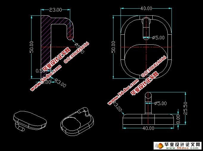
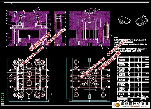
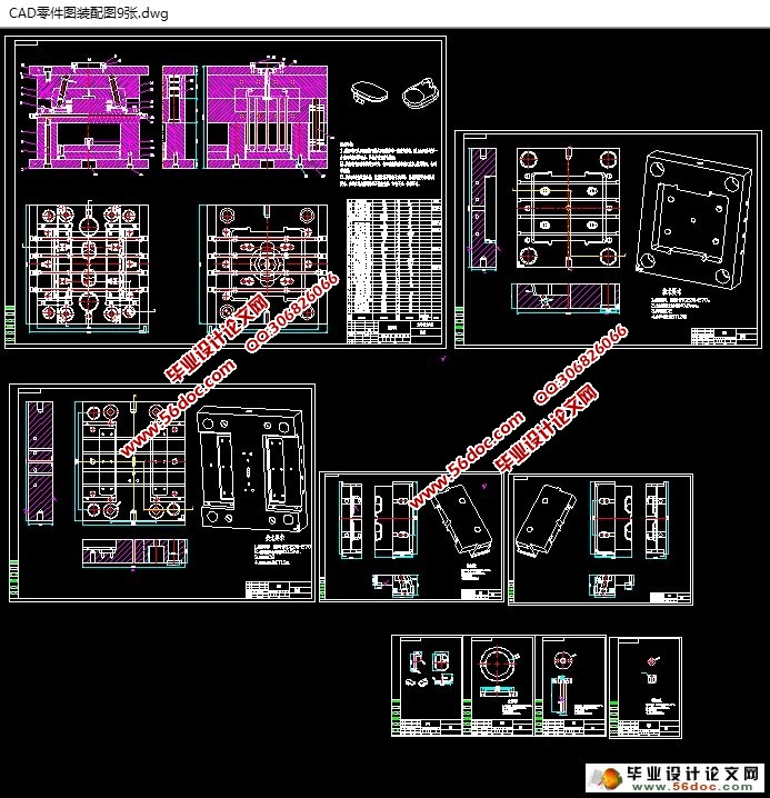
本文是针对塑料挂钩的注塑模具设计,介绍了挂勾注射成型的基本过程,单分型面注射模具的工作原理与结构,对注塑挂钩提出了基本的设计原则;简单的讲述了设计挂钩成型的工艺分析,遴选注塑机,思考和绘出浇注系统,设计成型零件,脱模取件机构,冷却系统的过程,并对模具的设想图也作了相关的介绍。同时,也运用了CAD软件绘制模具装配图和ProE软件进行产品设计、注射模结构设计和总配图。
关键词:注塑模具;挂勾;模具结构;ProE;CAD
Abstract
Plastic products used in society and life has occupied many areas, and in all walks of life, the plastic also provides an important force for its development. Plastic molding production, modernization and advanced mold design, mold manufacturing, high-quality, high-quality mold materials, processing technology and reasonable molding equipment and molding these conditions are closely related to the quality of plastic parts.
This article is for plastic injection mold design hook, hook describes the basic injection molding process, a single injection mold parting line of work principle and structure, injection molding hooks put forward the basic design principles; simply tells the hook shaped design process analysis, selection of injection molding machines, thinking and draw the gating system, molded part design, mold release pickup mechanism, cooling system, and also made a mold of FIG idea related to the introduction. It also used the CAD software to draw the mold assembly drawings and ProE software product design, injection mold structure design and general distribution map.
Key words: injection mold; hook; mold structure; ProE; CAD

目 录
摘 要 1
Abstract 2
目 录 3
概 论 1
第 1 章 塑料挂钩的工艺分析和技术要求 3
1.1 塑料挂钩的技术要求 3
1.2 塑件材料的特性 4
1.2.1 物理和化学性能 4
1.2.2 成型性能 4
1.2.3 典型的适用范围 4
1.3 塑料制件的工艺分析 5
1.3.1 塑件结构工艺性的特点 5
1.3.2 塑料制件成型工艺性要求 5
1.3.3 塑件的尺寸 5
1.3.4 塑件的脱模斜度 5
第 2 章 注塑成型机的选择和型腔数的确定 6
2.1 选择注射成型机 6
2.1.1 计算塑件的体积和投影面积 6
2.1.2 锁模力 6
2.1.3 注塑机的选择与主要参数 7
2.2 注射机的校核 7
2.2.1 注塑压力的校核 7
2.2.2 塑件锁模力的校核 8
第 3 章 浇注系统的结构设计 9
3.1 分型面的设计 9
3.1.1 分型面的概念 9
3.1.2 分型面的位置确定 9
3.2 确定型腔数量及排列方式 10
3.2.1 单型腔与多型腔 10
3.2.2 型腔的排列方式 10
3.3 设计浇注系统 11
3.3.1 浇口的设计 11
3.3.2 主流道的设计 13
第 4 章 成型零件的设计 14
4.1 成型零件结构设计 14
4.1.1 凹模 14
4.1.2 凸模 15
4.1.3 滑块的设计 16
4.2 模具成型零件的工作尺寸的计算 17
4.2.1塑件成型的最大尺寸计算 17
4.2.2 凹模和凸模的尺寸计算 18
第 5 章 导向与脱模机构的设计 21
5.1 导向机构作用和设计 21
5.1.1 导向机构的作用 21
5.1.2导柱导向机构 21
5.2 导柱和导套 21
5.2.1 导柱的设计 22
5.2.2 导套的设计 22
5.2.3 导向孔的总体布局 23
5.3 推出机构的设计 24
5.3.1 推出机构的介绍和设计原则 24
5.3.2 塑件的推出机构与计算 24
第 6 章 侧向分型和抽芯机构的设计 26
6.1 斜导柱侧向分型与抽芯机构的设计 26
6.2 斜导柱侧向分型与抽芯机构的参数计算 27
第 7 章 冷却系统与排气系统的设计 30
7.1 模具温度对塑件的影响 30
7.1.2 模具温度调节 30
7.1.2 设计原则 31
7.2 冷却系统的结构设计 31
7.3 排气系统 32
7.3.1 排气不良的危害 32
7.3.2 排气系统的设计 32
第 8 章 模具的装配总图 33
8.1 注塑模具的模架 33
8.2 总装图 33
设计小结 35
致 谢 36
参考文献 37
