衬圈模具设计(含CAD零件图装配图)
无需注册登录,支付后按照提示操作即可获取该资料.
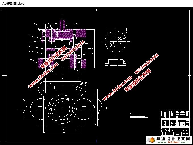
衬圈模具设计(含CAD零件图装配图)(文献综述,论文说明书7900字,CAD图8张)
摘 要
本次设计为衬圈的模具设计,材料为08F。成型该零件需经落料、冲孔、翻边等多个工序。研究该课题是为了更好的利用CAD、CAE等技术进行并优化模具设计,提高生产效率、提高产品质量、降低成本,使我们的设计水平得到切实提高。
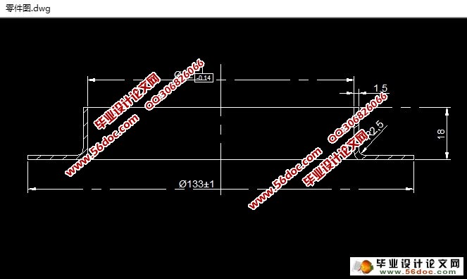
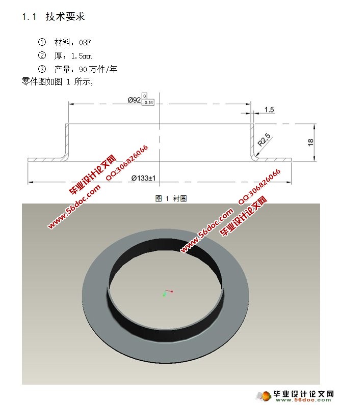
该零件为薄板类零件,形状简单且对称,外形光滑、圆整,尺寸精度和断面质量要求不高,翻边高度为18mm,翻边高度不高,外形最大尺寸为Ø133,属于小型零件。工件材料为08F钢,属于优质碳素结构钢(平均含碳量为0.08%),塑性好。冲压可以达到的公差等级为IT10-IT13,故IT10级的精度可以达到零件所需的要求。该零件的基本工序可以初步定为落料,冲孔,翻边。
关键词:冲孔;翻边;复合模
ABSTRAC
The bushing is designed to mold design, material 08F-HF. The molded part is subject to more than one step blanking, punching, flanging and so on.study of the subject is to make better use of CAD, CAE and other technologies and optimize mold design, improve production efficiency, improve product quality, reduce costs and make our design level has been effectively improved.
This part is a thin plate parts, a simple shape and symmetrical a sleek, rounded, dimensional accuracy and quality of less demanding sections, flange height of 18mm, flanging high is not high, the maximum size of shape to Ø133, are small parts. Can workpiece material 08F steel, are high-quality carbon structural steel (average carbon content of 0.08%), good plasticity. stamping can be up to tolerance class IT10-IT13, IT10 it can reach the level of precision parts required requirements. This part basic guarantee basic process may Connecticut to an initial period of blanking punching composite, turn edges.
Keywords: punching; flanging; Compound Die


目 录
摘 要 2
ABSTRAC 3
目 录 4
绪 论 6
1. 零件及工艺性分析 8
1.1 技术要求 8
1.2 读产品图,分析冲压工艺性 9
2. 分析计算确定工艺方案 10
2.1 判断能否一次翻边 10
2.2计算预冲孔大小 10
2.3计算翻边极限高度 10
2.4 确定工艺方案 11
3. 主要工艺参数的计算 13
3.1 确定排样、裁板方案 13
3.2 计算工艺力 14
3.2.1 翻边力 14
3.2.2 翻边卸料力 14
3.3 冲压设备选取 15
4. 编写冲压工艺过程卡 16
5. 模具结构设计 17
5.1 翻边凸模 17
5.2 翻边凹模 18
5.3 凸模固定板 19
5.4 垫板 20
5.5 卸料弹簧 21
5.6 卸料板 22
6. 选用模架、确定闭合高度及总体尺寸 24
7. 编制冲压工作零件工艺卡 25
7.1 翻边凸模的选材、热处理及加工工艺过程 25
7.2 翻边凹模的选材、热处理及加工工艺过程 25
7.3 卸料板的选材、热处理及加工工艺过程 26
7.4 模座的选材、热处理及加工工艺过程 26
7.5 导柱、导套的选材、热处理及加工工艺过程 26
8. 模具结构图 28
结束语 30
致 谢 31
参考文献 32
