
Φ17×10密封盖注塑模具设计(含CAD零件装配图)
无需注册登录,支付后按照提示操作即可获取该资料.
Φ17×10密封盖注塑模具设计(含CAD零件装配图)(任务书,设计说明书10000字,CAD图纸5张)
摘 要
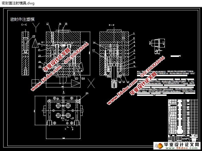
本课题就是做密封件的模具设计,通过对产品的做工分析和比较,最后做出可以一下做四件产品的注射模。这个课题简述了怎么做塑件的一些原理,从塑件的结构,到涉及到的所有模具,所有其中的各种系统都有详细的设计说明。就密封件的具体结构看,我们应该选择点浇口的单分型面注射模具。因为塑件本身没有口子,所以不用用滑块结构。其优点是结构简单,使模具在开模的时候简单,很大的减少了模具的成本。通过这次设计证明模具达到密封件的工艺要求。
经过本设计,使我们对注塑模具又一个认识,了解它的结构及工作原理;通过对二维软件学习,使我们学会了一些零件的外形,从而有效地提高工作效率。
关键词: 点浇口 ; 密封件 ; 注射模 ; 单分型面;
Abstract
Now very industrial types in growth in the world, including plastic is one of the plastic mould is developing rapidly, therefore, the research injection mold to understand the plastic product the production process and improve the quality of products has great significance.
This topic is to be the seal of mold design, through the work of product analysis and comparison, finally can make the injection mould for four more products. This topic describes how to do the principle of the plastic parts, from the structure of plastic parts, to involve all of the mold, all the various systems have a detailed design specifications. Seal of concrete structure, we should be the option gate single parting surface injection mould. Because itself has no cut plastic, so you don't have to use the slider structure. Its advantages are simple structure, make the mould in the mould was simple, a lot of reduce the cost of the mould. Through this design proves that mould meet the process requirements of the seals.
Through this design, to our understanding of injection mold and a, understand its structure and working principle; Based on two-dimensional learning software, we learn to make the appearance of some parts, so as to effectively improve the work efficiency.
Key words: point gate; The seals; Injection mould; Single parting surface;
目 录
第一章引言 1
1.1 课题的来源、目的、意义 1
1.1.1 课题的来源 1
1.2 主要内容和工作方法 2
1.2.1 主要内容 2
1.2.2 工作方法 2
1.3 设计中应注意的问题 3
第二章模具结构形式及注射机的初步确定 3
2.1 塑件成形工艺的可行性性分析 3
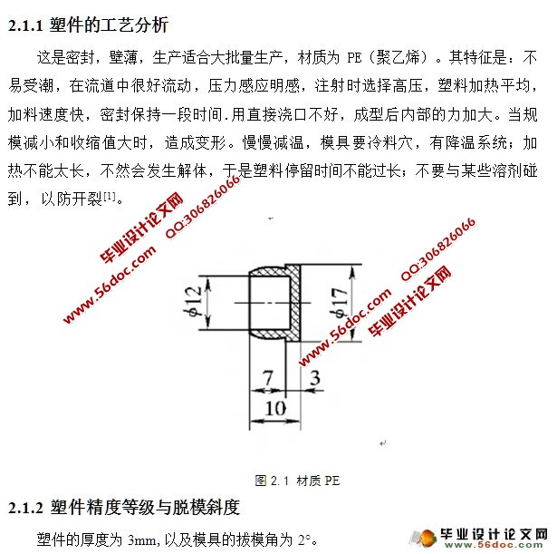
2.1.1 塑件的工艺分析 3
2.1.2 塑件精度等级与脱模斜度 4
2.1.3 热塑性塑料PE的成型过程 4
2.1.4 PE的注射机工艺参数 5
2.1.5 PE主要性能指标 5
2.2 拟定模具结构形式 6
2.2.1 分型面位置的确定 6
2.2.2 型腔数目的确定及排位方式的确定 6
2.2.3 模具结构形式初步确定 6
2.3 注射机型号确定 7
2.3.1 注射量的计算 7
2.3.2 选择注射机 7
2.3.3 注射机主要技术参数 7
2.3.4 注射机相关参数的校核 8
第三章浇注系统的设计 9
3.1 主流道的设计 9
3.1.1 主流道设计要点 9
3.1.2 主流道的尺寸 10
3.1.3 主流道的凝料体积 10
3.1.4 主流道当量半径 10
3.1.5 主流道的衬套形式 10
3.2 分流道的设计 12
3.2.1 分流道的形状及尺寸 12
3.2.2 分流道的布置形式 13
3.3 浇口的设计 13
3.3.1浇口的选择 14
3.3.2 浇口长度、宽度的确定 14
3.4 浇注系统的平衡 14
3.5 冷料穴和拉料杆的设计 14
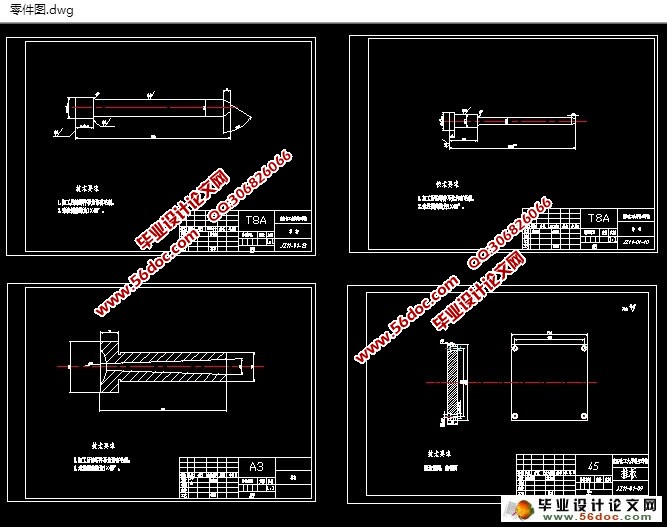
第四章成型零部件的设计 15
4.1 成型零部件的结构设计 15
4.1.1 凹模 15
4.1.2 凸模和型芯 15
4.1.3 成型零部件钢材的选用及技术要求 15
4.2 成型零部件工作尺寸的计算 16
4.2.1 塑料成型收缩率的计算 16
4.2.2 型腔和型芯径向尺寸的计算 16
4.2.3 型腔深度和型芯高度的尺寸计算 16
4.3 模具型腔侧壁和动模垫板厚度的计算 17
4.3.1 凹模侧壁厚度计算 17
4.3.2 动模垫板厚度计算 17
第五章模架设计和其它部件及标准件选用 18
5.1 模架的选用 18
5.2 标准件的选用 19
5.3 合模导向机构的设计 19
5.4 脱模推出机构的设计 20
5.4.1 脱模力的计算 20
5.4.2 脱模推出机构的选择 21
5.5 排气系统的设计 22
5.6 温度调节系统的设置 22
5.6.1 冷却介质 23
5.6.2 冷却系统的简略计算 23
第六章模具装配图的设计 24
6.1 模具装配的技术要求 24
6.2 模具工作过程 25
参考文献 26
致谢 28