VF-0.8/50空气压缩机的设计(整体设计编程,一、二级缸设计)
无需注册登录,支付后按照提示操作即可获取该资料.
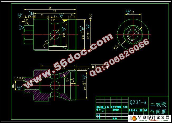
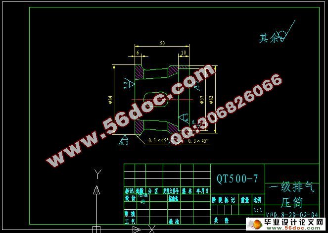
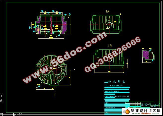
VF-0.8/50空气压缩机的设计(整体设计编程,一、二级缸设计)(任务书,开题报告,外文翻译,进度计划表,论文说明书26000字,cad图纸4张)
摘 要
压缩机是用来提高气体压力和输送气体的机械。从能量转换的方式来看, 压缩机是属于将原动机的动力能转变为气体压力的工作机。本设计为中压活塞式空气压缩机设计。活塞式压缩机与其他类型的压缩机相比,其优点是:压力范围最广、效率高、适应性强,即排气量范围较广,且不受压力高低的影响。活塞式压缩机应用较广泛,例如在吹瓶机、核电站、仪表等方面,特别是在中小制冷范围内成为应用最广,生产批量最大的一种机型。
本次整个设计的内容包括压缩机的总体、气缸及基本部件的设计。主要通过热力计算和动力计算来确定压缩机的总体结构方案设计,和各种零部件的设计。同时,在本次的设计过程中,开发了一个计算机软件来完成热力计算和动力计算,借助AutoCAD绘图软件绘图。
关键词:活塞式压缩机;计算机编程;热力计算;动力计算;主要零部件设计
Abstract
The compressor is used to increase the gas pressure and gas transportation machinery. Judging from the energy conversion, the compressor is working machine, which can transform the prime mover into gas pressure. This design is for the medium-pressure piston air compressor. Compared with other types of compressors, advantages of piston compressor are: pressure range is the most extensive, high efficiency, adaptability. That means a wider range of displacement and pressure level will not affect it. The piston compressor is used widely, such as blowing machine, nuclear power plants, instrument, particularly in small and medium-sized refrigeration. It is also the largest production volume of a model.
The entire design includes the design of the compressor overall, the cylinder and the basic member. The compressor overall structure of the program and various parts of the design is mainly determined by thermodynamic calculation and dynamic calculation.In the design process, I develop a computer software to complete the thermodynamic calculation and dynamic calculation, drawing with AutoCAD drawing software.
Key words: piston compressor; computer programming; heating calculation; dynamic calculation; structural design


目 录
摘 要 III
ABSTRACT IV
目 录 V
1 绪论 1
1.1本课题的研究内容和意义 1
1.2国内外的发展概况 1
1.3本课题应达到的要求 2
2总体设计方案 3
2.1设计参数及依据 3
2.1.1 设计参数 3
2.1.2 设计活塞压缩机应符合以下基本原则 3
2.2 主要结构参数的选择 3
2.2.1 转速n 3
2.2.2 行程S 3
2.2.3 活塞平均速度 4
2.3 结构方案的选择 4
2.3.1 气缸排列的型式及其选择 4
2.3.2 运动机构的结构及选择 5
2.4 中间冷却器 5
3 热力计算 7
3.1 概述 7
3.2 热力计算原始数据 13
3.3 初步确定各级名义压力 15
3.4 计算各级排气温度 17
3.5 确定各级的排气系数 19
3.5.1 容积系数 19
3.5.2 压力系数 21
3.5.3 温度系数 21
3.5.4 气密系数 21
3.5.5 排气系数 22
3.6 确定各级干气系数 22
3.7确定各级抽气系数 22
3.8 确定各级气缸行程容积 22
3.9 确定各级气缸直径 24
3.10 圆整后各级名义压力及温度 26
3.10.1 确定圆整后各级实际行程容积 26
3.10.2 求各级压力修正系数 、 27
3.10.3 修正后各级名义压力及压力比 29
3.10.4 修正后各级排气温度 30
3.11 计算活塞力 31
3.11.1 计算气缸内实际吸排气压力 31
3.11.2 计算各列的活塞力 32
3.12 计算轴功率,选取电机 35
3.12.1 计算各级指示功率 35
3.12.2 整个机器总指示功率 36
3.12.3 轴功率 36
3.12.4 选择电机 36
4 动力计算 37
4.1 概述 37
4.2 初始数据 37
4.3 作各级气缸设计示功图 37
4.4 作往复惯性力图 44
4.5 计算各级往复摩擦力 47
4.6 作综合活塞力曲线图 47
4.7 作切向力图 52
4.8 确定飞轮距 56
5 主要零部件设计 58
5.1 一、二级气缸设计 58
5.1.1 气缸结构型式 58
5.1.2 气缸结构设计 58
5.2 一、二级活塞组件 61
5.2.1 活塞 61
5.2.2 活塞环与活塞环的润滑 62
5.3 一、二级气阀 65
5.3.1 气阀的基本要求 65
5.3.2 气阀主要参数的确定 65
结论与展望 71
6.1 结论 71
6.2 不足之处及未来展望 71
致谢 72
参考文献 73
附录 74
