连杆端面平行度自动检测仪的设计
无需注册登录,支付后按照提示操作即可获取该资料.
连杆端面平行度自动检测仪的设计(选题审批表,任务书,开题报告,中期检查表,毕业论文说明书13000字,CAD图纸11张)
摘 要:连杆是汽车发动机的主要传力构件之一,常处于高速运动状态,因此要求与其它零件间具有较高的配合精度。因而连杆的检测是生产中频繁而又不可缺少的环节。目前我国连杆检测对于平行度的检测主要采用手工检测。本选题的设计是专门用来检测连杆端面的平行度,它避免了手工检测可能带来的人为因素导致的误差,极大的提高了检测效率同时也提高了检测的精度。
关键词:连杆;平行度检测;端面
The Design of Automatic Detector for Parallelism of Both Side of Connecting Rod
Abstract:The connecting rod is one of the main power transmission components for automotive engine, it often in a state of high-speed motion, thus requiring higher accuracy connect with other parts. So the detection of the connecting rod is frequent and indispensable part of the production. Linkage detection in China is using manual testing for parallelism detection. The design of this topics is designed to detect rod end of the parallelism, it avoids the errors caused by manual testing potential human factors, and greatly improves the detection efficiency but also to improve the detection accuracy.
Keywords:Connecting rod ;Parallel testing ;End face


目 录
摘要…………………………………………………………………………………………1
关键字………………………………………………………………………………………1
前言…………………………………………………………………………………………1
1 方案的拟定 ……………………………………………………………………………2
1.1 行位误差测量的基本原则 ……………………………………………………2
1.2 连杆端面平行度公差分析 ……………………………………………………3
1.3 原始数据的采集 ………………………………………………………………3
1.4 原始数据的处理 ………………………………………………………………4
1.5 端面平行度子程序的设计 ……………………………………………………4
2 自动检测系统的设计 …………………………………………………………………5
2.1 主机部分…………………………………………………………………………5
2.2 传感器测量部分…………………………………………………………………5
2.3 电机及驱动部分…………………………………………………………………7
2.3.1 本设计中用于工作台进给的步进电机的选择…………………………8
2.3.2 两回转支座的回转运动的电机…………………………………………9
2.3.3 回转支座上装传感头的滑座Y向的进给运动的电机…………………9
2.4 机械机构部分 …………………………………………………………………9
2.4.1 工作台的设计…………………………………………………………10
2.4.2 滚珠丝杆螺母副的设计………………………………………………10
2.4.3 导轨副的设计…………………………………………………………12
2.4.4 齿轮传动的设计计算…………………………………………………13
2.4.5 联轴器的选择…………………………………………………………14
2.4.6 传动轴的设计…………………………………………………………15
2.4.7 位置检测元件的设计…………………………………………………16
3 自动检测装置的软件设计……………………………………………………………17
3.1 数据处理程序…………………………………………………………………17
3.2 数据自动采集接口……………………………………………………………17
4 总结……………………………………………………………………………………18
参考文献 …………………………………………………………………………………19
致谢 ………………………………………………………………………………………20
附图 ………………………………………………………………………………………20
附图:
附图1.进给齿轮零件图
附图2.从动齿轮零件图
附图3.进给轴端盖零件图
附图4.从动轴端盖零件图
附图5.进给传动齿轮轴零件图
附图6.从动轴零件图
附图7.轴承座零件图
附图8.工作台零件图
附图9.旋转支座零件图
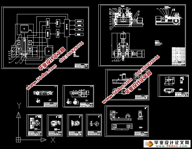
附图10.装置原理图
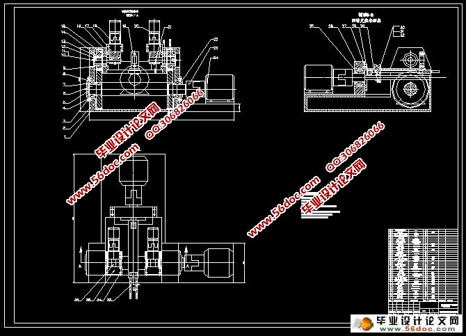
附图11.装配图
