基于液压控制的翻转机械手的设计
无需注册登录,支付后按照提示操作即可获取该资料.
基于液压控制的翻转机械手的设计(含选题审批表,任务书,开题报告,中期检查表,论文说明书14000字,CAD图纸6张,液压原理图)
摘 要:随着工业自动化发展的需要,机械手在工业应用中越来越重要。文章主要叙述了机械手的设计计算过程 。文章主要叙述了机械手的设计计算过程 。首先,本文介绍机械手的作用,机械手的组成和分类,说明了自由度和机械手整体座标的形式。同时,本文给出了这台机械手的主要性能规格参量。文章中介绍了搬运机械手的设计理论与方法,全面详尽的讨论了搬运机械手的手部、腕部、手臂以及机身等主要部件的结构设计。
关键词:机械手;液压传动;液压缸;行程开关;方向控制阀
The Design Of Overturn Manipulator Based On Hydraytic Control
Abstract:The applying of the manipulators are more and more important in the industry, with the development of industrial automation. The paper mainly narrated the design and caculation of and transfer manipulator.The first, the paper introduces the function,composing and classification of the manipulator, tells out the free-degree and the form of coordinate. At the same time, the paper gives out the primary spcification parameter of this manipulator.This article system elaboration industry manipulator`s design theory and method. The comprehensive exthaustive discussion has transported manipulator`s hand, the wrist, the arm, the fuselage and so on, which the major structural design compulation.
Key words: manipulator; hydraulic power transmission; hydraulic cylinder; route of distance switch; direction contorl tap
驱动机构
驱动机构是工业机械手的重要组成部分。根据动力源的不同, 工业机械手的驱动机构大致可分为液压、气动、电动和机械驱动等四类。采用液压机构驱动机械手,结构简单、尺寸紧凑、重量轻、控制方便。
控制系统分类
在机械手的控制上,有点动控制和连续控制两种方式。大多数用插销板进行点位控制,也有采用可编程序控制器控制、微型计算机控制,采用凸轮、磁盘磁带、穿孔卡等记录程序。主要控制的是坐标位置,并注意其加速度特性。
机械手座标形式的确定
常用工业机械手按驱动方式分:直角座标式、圆柱座标式、球座标式、多关节式几种类型,如图2.1所示。其中直角座标式手臂可沿X、Y、Z座标轴作直线移动,即伸缩、升降和横移。其特点是直观性好,所占空间位置大。根据设计任务所需,特选定为直角座标式。


#p#副标题#e#
目 录
1 绪论………………………………………………………………………………1
1.1 前言………………………………………………………………………1
1.2 工业机械手在生产中的应用……………………………………………2
1.3 机械手的组成………………………………………………………………3
1.3.1执行机构……………………………………………………………3
1.3.2驱动机构……………………………………………………………4
1.3.3控制系统分类………………………………………………………4
2 总体布局设计方案…………………………………………………………………4
2.1 机械手的确定………………………………………………………………4
2.2驱动机构的选择……………………………………………………5
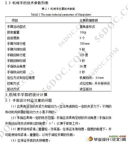
2.3 机械手的技术参数列表…………………………………………………6
3 机械手手部的设计计算……………………………………………………………6
3.1 手部设计时应注意的问题…………………………………………………6
3.2 典型的手部结构……………………………………………………………6
3.3 机械手手部结构及驱动的设计计算………………………………………7
3.3.1选择手部的类型及夹紧装置………………………………………7
3.3.2手指夹紧力及液压缸驱动力的计算液压缸的选用………………7
3.4 机械手手指部的设计计算………………………………………………9
3.4.1齿轮齿条传动机构的设计计算……………………………………9
3.4.2手指指部的设计计算……………………………………………13
3.4.2手指指部齿轮安装销的设计计算………………………………13
4 机械手腕部的设计计算…………………………………………………………13
4.1 机械手腕部结构及运动分析……………………………………………13
4.2 机械手腕部驱动装置的设计计算及选用………………………………14
5 机械手臂部的设计及有关计算…………………………………………………15
5.1 臂部设计时应注意的问题………………………………………………15
5.2 手臂的典型结构以及结构的选择………………………………………15
5.3 手臂Z方向升降运动的受力分析及其计算……………………………16
5.4手臂Z方向升降运动液压缸结构尺寸的设计计算及选用……………18
6 机身的设计…………………………………………………………………19
6.1 机身的概述……………………………………………………………19
6.2 机身设计时应注意的问题……………………………………………20
7 液压元件及动力机的设计选择………………………………………………20
7.1 液压泵的选择……………………………………………………………20
7.2动力机选择……………………………………………………………20
7.3 油管的设计………………………………………………………………21
7.4 油箱的设计………………………………………………………………21
7.5 液压元件的选择…………………………………………………………22
7.6 液压油的选用…………………………………………………………23
8 液压系统的验算………………………………………………………………24
8.1 压力损失的验算…………………………………………………………24
8.1.1回路压力损失的验算……………………………………………24
8.1.2局部压力损失验算……………………………………………25
8.2 计算液压系统的发热温升………………………………………………25
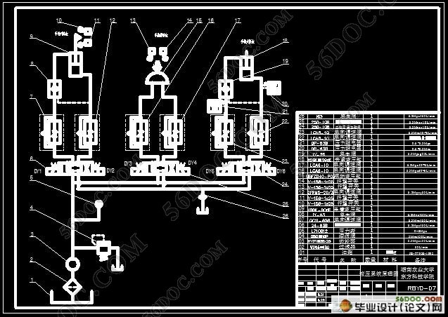
9 液压系统工作过程简述………………………………………………………26
10 结束语…………………………………………………………………………27
参考文献
致谢
附件
