Z30130X31型钻床控制系统的PLC改造(含cad零件图和装配图)
无需注册登录,支付后按照提示操作即可获取该资料.
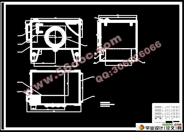
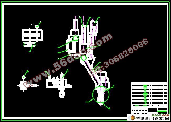
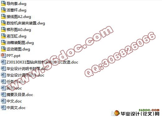
Z30130X31型钻床控制系统的PLC改造(含cad零件图和装配图)(任务书,调研报告,外文翻译,毕业论文28000字,答辩PPT,cad图纸8张)
摘 要
Z30130X31型摇臂钻床属于大型立式钻床,其传统的控制方式是利用继电器接触器原理控制。由于利用继电器接触器控制系统比较复杂,难于操作;因此本次设计是将其改造成为利用PLC控制,这样既可以提高生产效率,也可以增加其使用寿命。
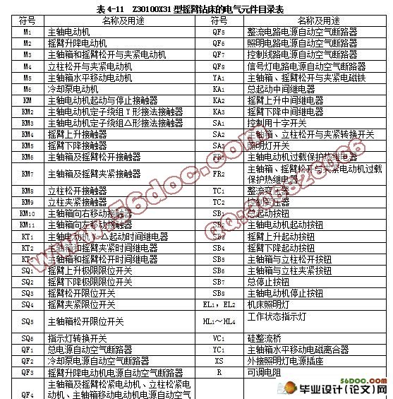
首先通过对钻床工作原理的了解,然后对PLC的硬件和软件进行设计。根据钻床的工作要求选择合理的工作器件如:继电器,接触器等等,然后编写相应的程序语句表并绘制梯形图,再根据输入输出点数选择PLC型号,输入点数:22输出点数:17,所以本次设计选择FX2N-48MR型PLC并绘制硬件接线图;最后对程序进行模拟调试。
关键词:PLC、电动机;行程开关;断路器;控制按钮;控制开关;工作指示灯。
Abstract
Z30130X31-arm drilling is a large vertical drilling, the traditional control method is the use of relay contacts Principle control. The use of the relay contactor control system more complicated and difficult operation, therefore this design is its use of a PLC control, this can enhance the efficiency of production and can also increase their service life.
By drilling the first principle of understanding, and then the PLC hardware and software design. According to drilling requirements for the work of the work of a reasonable choice of devices such as: relays, contacts, etc., and then the preparation of the corresponding procedures and the mapping of ladder diagram sentences table, the light input and output points choose PLC models, the importation of points: 22 output points: 17, Therefore, this design options FX2N-48MR PLC and the mapping of hardware wiring diagram; Finally, the simulation debugging procedures.
Key words: PLC; motor; trip switch circuit breaker; control button control switch; work light.
机床的主要参数
1. 机床的主要参数
(1)最大钻孔直径 100mm
(2)主轴中心线至立柱母线距离:最大 3150mm
最小 570mm
(3)主轴箱水平移动距离 2580mm
(4)主轴端面至底座工作面距离:最大 2500mm
最小 750mm
(5)摇臂升降距离 1250mm
(6)摇臂升降速度 0.61m/min
(7)摇臂回转角度 360度
(8)主轴圆锥孔 莫氏6号
(9)主轴转速范围 8~1000r/min
(10)主轴转速级数 22级
(11)主轴进给量范围 0.06~3.2mm/r
(12)主轴进给量级数 16级
(13)主轴行程 500mm
(14)刻度盘每转钻孔深度 170mm
(15)主轴允许最大扭转力矩 2450N•m
(16)主轴允许最大进给抗力 49×10 3.N
(17)主电机功率 15kw
(18)摇臂升降电机功率 3kw
(19)主轴箱及摇臂液压夹紧电机功率 0.75k
(20)立柱液压夹紧电机功率 0.75kw
(21)主轴箱水平移动电机功率 0.25kw
(22)主轴箱水平移动速度 1.6m/min
(23)冷却泵电机功率 0.09kw


目 录
第一章 引言•••••••••••••••••••••••••••••••••••••••••••••••••••••••••••••••1
第二章 机床的主要参数及钻床的机械及运动形式•••••••••••••••••••••••••••2
第三章 继电器接触器控制原理•••••••••••••••••••••••••••••••••••••••••••••4
3.1制线路特点与电气线路概述•••••••••••••••••••••••••••••••••••••••••4
3.2控制原理分析及分立控制线路•••••••••••••••••••••••••••••••••••••••5
第四章PLC控制系统的硬件设计•••••••••••••••••••••••••••••••••••••••••••10
4.1电动机的选型•••••••••••••••••••••••••••••••••••••••••••••••••••••••10
4.2接触器的选择•••••••••••••••••••••••••••••••••••••••••••••••••••••••12
4.3自动空气断路的选型••••••••••••••••••••••••••••••••••••••••••••••••15
4.4热继电器的选用•••••••••••••••••••••••••••••••••••••••••••••••••••••16
4.5中间继电器的选型•••••••••••••••••••••••••••••••••••••••••••••••••••18
4.6万能转换开关的选型•••••••••••••••••••••••••••••••••••••••••••••••••18
4.7电磁铁的选型•••••••••••••••••••••••••••••••••••••••••••••••••••••••19
4.8按钮的选型••••••••••••••••••••••••••••••••••••••••••••••••••••••••••19
4.9位置开关的选型•••••••••••••••••••••••••••••••••••••••••••••••••••••19
4.10导线的选型••••••••••••••••••••••••••••••••••••••••••••••••••••••••20
4.11变压器的选型••••••••••••••••••••••••••••••••••••••••••••••••••••••20
4.12机床电气控制系统的工艺设计••••••••••••••••••••••••••••••••••••••23
4.13电气元件布置图的绘制•••••••••••••••••••••••••••••••••••••••••••••24
4.14电气接线图的绘制•••••••••••••••••••••••••••••••••••••••••••••••••25
4.15 可编程控制器•••••••••••••••••••••••••••••••••••••••••••••••••••••26
4.16三菱PLC指令系统••••••••••••••••••••••••••••••••••••••••••••••••••35
第五章 PLC控制系统软件设计••••••••••••••••••••••••••••••••••••••••••••••37
5.1输入地址分配•••••••••••••••••••••••••••••••••••••••••••••••••••••••37
5.2输出地址分配•••••••••••••••••••••••••••••••••••••••••••••••••••••••37
5.3接线图••••••••••••••••••••••••••••••••••••••••••••••••••••••••••••••38
5.4程序语句表•••••••••••••••••••••••••••••••••••••••••••••••••••••••••39
第六章 程序模拟调试•••••••••••••••••••••••••••••••••••••••••••••••••••••••42
第七章 第七章 总结•••••••••••••••••••••••••••••••••••••••••••••••••••••••••••••••44
致谢••••••••••••••••••••••••••••••••••••••••••••••••••••••••••••••••••••••••45
参考文献•••••••••••••••••••••••••••••••••••••••••••••••••••••••••••••••••••46
