基于MSP430的节能路灯控制设计
无需注册登录,支付后按照提示操作即可获取该资料.
基于MSP430的节能路灯控制设计(开题报告,论文17000字)
摘 要
随着生活水平的提高,路灯在我们日常生活中扮演的角色越来越重要,但是我国的电力资源十分有限,因此应使路灯在满足照明需求的同时更加节能。
本文介绍了一个由MSP430控制的节能路灯控制系统,本系统能根据当前时间、环境亮度等实际情况控制路灯的亮暗以及照明亮度,同时可以设置和显示时间,与传统的路灯控制方式相比,本系统的控制方式更加合理、智能,系统更加节能。
在本文中,首先讨论了设计本系统的背景与意义,提出了本课题的任务;接着详细地阐述了这个系统的方案选择、硬件电路设计与软件设计,在硬件电路设计中,详细地介绍了各个模块所使用的器件、芯片及工作原理,在软件设计中,介绍了主程序和主要的子程序的工作流程,讲解了子程序中一些关键的程序;最后简要地介绍了在调试过程中遇到的问题以及我个人的一些心得体会。
关键词:MSP430;路灯;节能
Energy-saving street lamp system controlled by MSP430
Abstract
With the improvement of living standards, the street lamp is playing a more and more important role in our daily life. However, the power resources of our country is very limited. So we should make the street lamp more energy-saving and meet the demand of lighting at the same time.
This paper introduces an energy-saving street lamp system controlled by MSP430. The system could control the LED light dim, bright, enhances or reduces the lighting levels according to the actual situations such as current time and environment brightness. The system could set and display the current time and date as well. Compared with the traditional street lamp control mode, the control of this system is more reasonable, intelligent and energy-saving.
In this paper, firstly, we discussed the background and significance of the design of the system, and put forward the tasks of this project. Then, the scheme choice, hardware circuit design and software design were described in detail. In the hardware circuit design, the devices, chips and operating principles of each module were introduced in detail. In software design, we described the working processes of the main program and the main subroutines, and explained some of the key procedures in the subroutine. At last, some problems that I encountered during debugging and my personal experiences were introduced in brief.
Key Words:MSP430; lamp; energy-saving


目 录
摘 要 I
Abstract II
第一章 绪 论 1
1.1 研究背景及意义 1
1.2 国内现状 1
1.3 课题任务 2
第二章 硬件电路设计 4
2.1 总体方案设计 4
2.2 光感模块 5
2.2.1 方案设计 5
2.2.2 器件简介 5
2.2.3 具体电路实现 6
2.3 时钟模块 7
2.3.1 方案设计 7
2.3.2 芯片简介 8
2.3.3 具体电路实现 8
2.4 按键设置模块 9
2.4.1 方案设计 9
2.4.2 具体电路实现 10
2.5 人体感应模块 10
2.5.1 方案设计 10
2.5.2 芯片简介 11
2.5.3 具体电路实现 12
2.6 单片机控制模块 12
2.6.1 方案设计 12
2.6.2 芯片简介 13
2.6.3 具体电路实现 14
2.7 LED输出电路 15
2.7.1 器件简介 15
2.7.2 具体电路实现 15
2.8 显示模块 15
2.8.1 方案设计 16
2.8.2 芯片简介 16
2.8.3 具体电路实现 18
第三章 软件设计 19
3.1 概述 19
3.2 时间设置及显示模块 20
3.2.1 显示模块 22
3.2.2 时钟模块 24
3.3 LED输出模块 26
3.5 LED灯调光方法 27
第四章 调试 28
4.1 焊接电路板 28
4.2 配置工程 29
4.3 调试过程 31
4.3.1 LED 输出模块 31
4.3.2 显示模块 33
4.3.2 系统调试 33
结 语 36
参考文献 37
致 谢 38
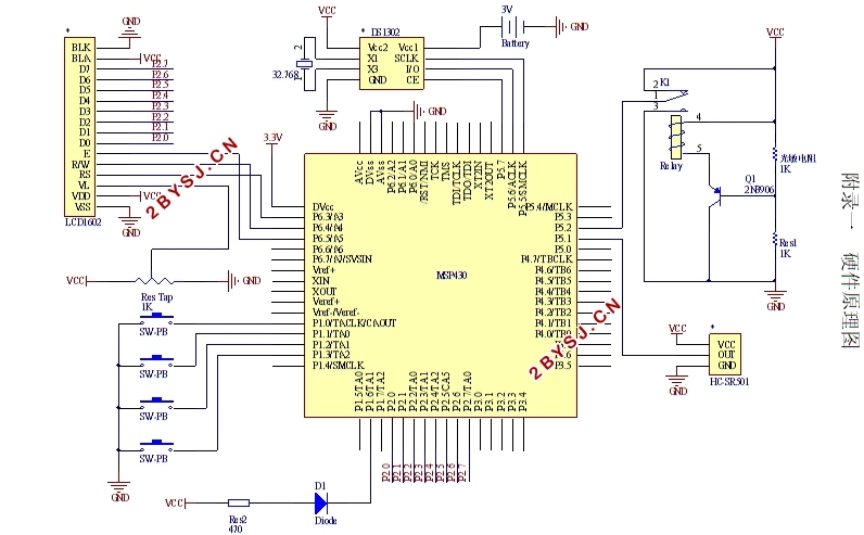
附录一 硬件原理图 39
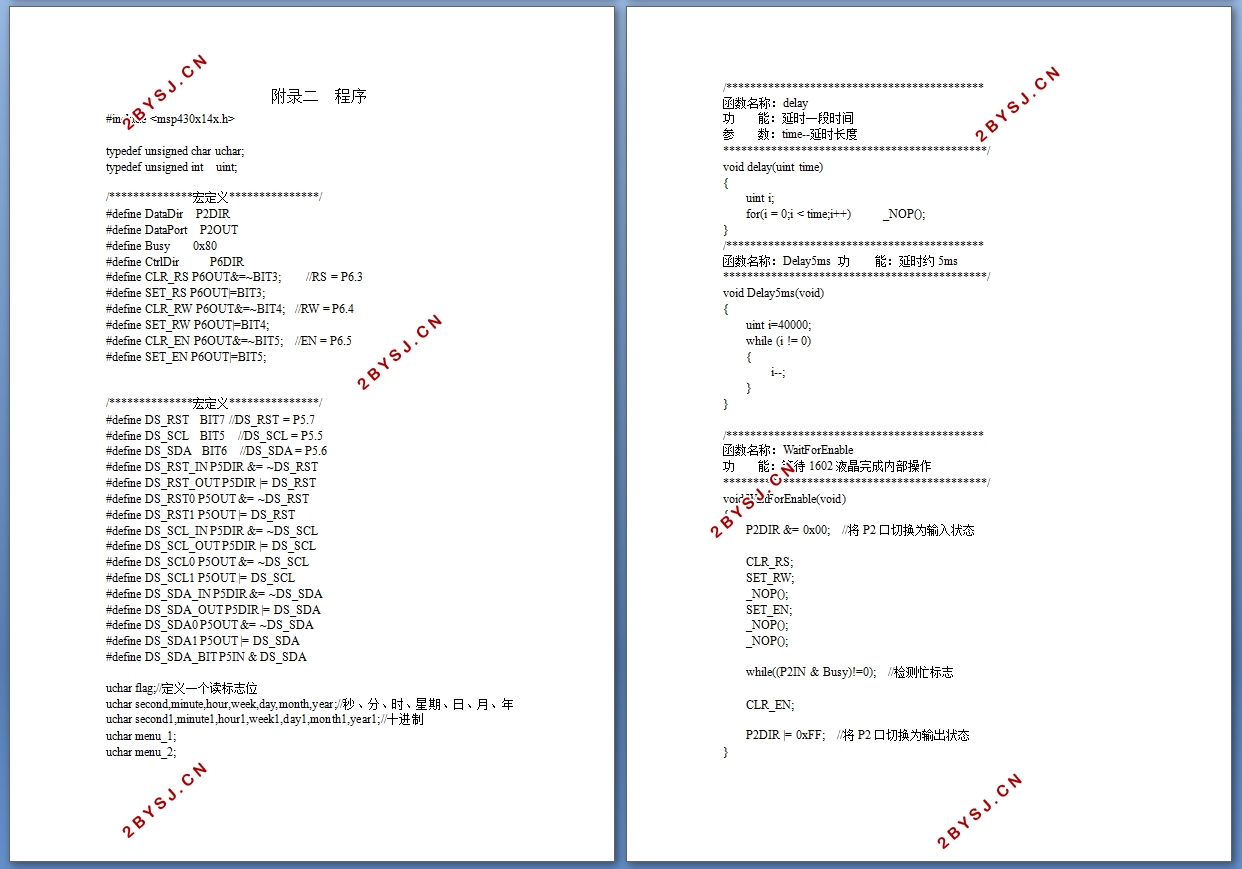
附录二 程序 40
