基于STM32的简易电阻测量仪的设计
无需注册登录,支付后按照提示操作即可获取该资料.
基于STM32的简易电阻测量仪的设计(任务书,开题报告,论文11000字)
摘 要
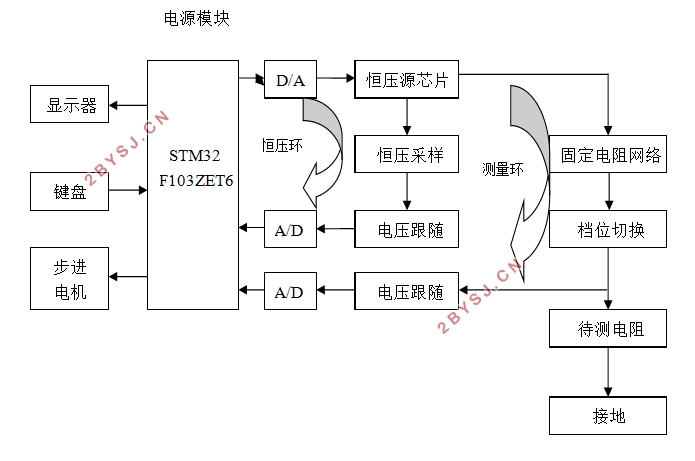
此次设计的测量仪主要由闭环恒压源电路、闭环测量电路、电机驱动电路,LCD显示电路四大部分构成,MCU为STM32系列中的STM32F103ZET6。设计中闭环恒压源电路包含数模转换器、恒压维持电路、电压跟随电路、模数转换器;闭环恒压源电路的主要作用是给芯片和模块分别提供恒压源。主体的闭环测量电路包括档位切换电路、电压跟随电路、虚拟触摸键盘、12位模数转换器;电机驱动电路由L298N电路为核心,加上步进电机、旋转式单圈电位器构成;液晶显示电路的主体是3.2寸的TFT–LCD。
此次设计的测量仪的基本原理如下:恒压源电路设定输出5V电压,经过档位切换电路、电压跟随电路后输出至单片机,单片机内部的ADC对信号进行处理后,通过程序运算得到被测电阻的阻值,最后经过单片机输出在液晶显示电路,显示电路显示电阻测量结果。
电机由单片机给电机驱动电路输入相应的指令来控制,通过电位器的旋转得到不同的阻值数据,测量得到的数据经过单片机内部程序计算处理后在LCD上显示出相应测量曲线。
该测量仪具备四个档位,100Ω档至1MΩ档,经仿真调试,最终100Ω档时平均误差为0.08%,1KΩ档时误差为0.05%,10KΩ档时误差为0.06%,1MΩ档时误差为0.08%,同时测量仪具备自动换挡功能并且能够筛选一定范围内的电阻。操作者能够通过键盘输入需求电阻阻值和允许误差范围,随后对电阻进行检测,LCD屏幕显示出被测电阻的阻值,且显示出该电阻是否符合设定的选择要求。
关键词:简易测量;恒压测量;档位切换;电阻筛选
Abstract
The measuring instrument is mainly composed of four parts: closed-loop constant voltage source circuit, closed-loop measuring circuit, motor driving circuit and LCD display circuit. The MCU is STM32F103ZET6 in STM32 series.In the design, the closed-loop constant voltage source circuit includes DAC, constant voltage circuit, voltage following circuit and ADC; the main closed-loop measurement circuit includes shift switching circuit, voltage following circuit, virtual touch keyboard, 12-bit ADC; the motor driving circuit is composed of L298N circuit, stepping motor and rotary single-loop potentiometer; the main body of LCD circuit is 3.2 inch TFT-LCD.
The basic principle of the measuring instrument is as follows: the constant voltage source circuit sets the output 5V voltage, which is output to the single chip computer through the shift switching circuit and the voltage following circuit. The signal is processed by the ADC inside the single chip computer, and the resistance value of the tested resistance is obtained by the program calculation. Finally, the resistance is output to the liquid crystal display circuit through the single chip computer, and the resistance measurement result is displayed by the display circuit.
Stepper motor is controlled by the MCU to input corresponding instructions to the driving circuit. Different resistance values are obtained by rotating potentiometer. The measured data are processed by the internal program of the MCU and displayed on the LCD screen.
The instrument has four gears, 100_gear to 1 M_gear. After simulation and debugging, the average error of 100_gear is 0.08%, the error of 1 K gear is 0.05%, the error of 10 K gear is 0.06%, and the error of 1 M gear is 0.08%.The operator can input the required resistance value and allowable error range through the keyboard, and then test the resistance. The screen shows the measured resistance value, and shows whether the resistance meets the set screening requirements.
Keywords:Simple measurement; Constant voltage measurement; Gear switching; Resistance selecting

目录
第1章绪论 1
一、研究现状 1
二、设计的基本内容及目标 2
第2章系统方案设计 3
2.1功能分析 3
2.2测量原理 3
2.3核心控制芯片 5
2.4档位切换模块 7
2.5 ADC采样电路 8
2.6显示模块 9
2.7键盘控制电路 9
第3章系统设计 11
3.1系统总体思路 11
3.2系统硬件模块设计 12
3.2.1硬件介绍 12
3.2.1.1芯片介绍 12
3.2.2 电阻触摸屏原理 15
3.2.3 触摸屏控制芯片 17
3.3电源电路设计 17
3.4恒压源电路设计 19
3.5档位切换电路设计 20
3.6电压跟随电路设计 21
3.7电机驱动电路设计 22
3.8软件设计 23
第四章系统仿真测试 24
参考文献 27
