基于STM32的超声波雷达系统设计(附程序代码)
无需注册登录,支付后按照提示操作即可获取该资料.
基于STM32的超声波雷达系统设计(附程序代码)(任务书,开题报告,外文翻译,论文14600字,程序代码,答辩记录,答辩PPT)
摘 要
本课题设计一个可对周围障碍物进行扫描和发现的超声波雷达系统。系统接收到启动指令后开始工作,当有目标物体出现后,采集当前的距离和角度信息,并将采集到的数据在下位机中处理之后通过通信接口发送给上位机进行显示。本文通过对测距方式的分析和比较,确定了由STM32单片机与US100超声波测距模块组成的雷达扫描系统,本文旨在将US100传感器与STM32微控制器相连接,利用步进电机以及通讯串口完成系统设计。本文中的雷达可以检测周围3厘米至4.5米的物体,同时考虑了温度对超声波的影响,并显示与物体之间的距离值。雷达可以360度全方位扫描周围障碍物,使用步进电机控制超声波测距模块,实现1.8度采集一个数据的功能。然后将数据呈现在LCD显示屏上,并通过串口发送到上位机,使电机转动与雷达扫描还有显示同步。
考虑到硬件平台设计问题,程序设计中加入了复位功能,即雷达扫描终止,电机控制超声波模块回到初始预置位置,保证雷达后续的运行不受影响。
关键词:单片机 超声波测距模块 雷达 步进电机 串口
The Design of Ultrasonic Radar System based on STM32
Abstract
A kind of ultrasonic radar was designed and implemented using STM32 MCU, which had the ability to detect objects surrounding center point. Compared with the traditional microcontroller,the basic frequency and the timer frequency of the STM32 microcontroller reach up to 72MHz,which improve the resolution of the measuring time. The PWM function of ultrasonic timer can be used to drive the launch of the ultrasonic transmitter, and the use of timer function input capture can help receive echo signals. The timer open will start PWM and input capture will beginning to ranging distance, and the superiority is that you can start PWM channel s to drive ultrasonic transmitter and input capture channel at the same time. The US100 sensor is connected with STM32 micro controller, and the system is completed by stepper motor and serial port design. This project considers the effect of temperature on ultrasound. The radar can detect objects between 3 and 4.5 meters, and shows the distance between objects. The radar can scan the surrounding obstacles in full 360 degrees. Use the stepper motor to control the ultrasonic range module to achieve a 1.8 degree acquisition of a data. The data display on the LCD and sent to the host computer via. Synchronize the motor movement with the radar scanning screen.
Taking into account the hardware platform design issues, the project added a reset code. After the radar scan shutdown, the motor control the ultrasonic module back to the initial position.
Key Words : MCU; Ultrasonic distance measurement module; Radar; Stepper motor; Serial port
课题分析
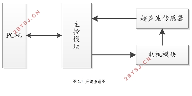
本课题设计一个可对周围障碍物进行扫描和发现的超声波雷达系统。系统接受到启动指令后开始360°全方位扫描,当扫描到障碍物后,采集当前的距离和角度信息,并将采集到的数据在下位机处理之后通过通信接口发送给上位机进行显示。系统通过主控板模块、电机模块、超声波传感器模块和PC机实现上述功能。而主控板模块的功能是接收到来自传感器的障碍物信息,然后对其进行相应的处理,再将这些信息转换为数据信息发送给上位机;超声波传感器的功能是采集周围障碍物与雷达系统的距离和角度信息,并传输给主控板,由于声速会受到工作环境的温度的影响,所以需要测量温度从而对测量距离进行相应的温度补偿;电机模块由电机驱动器进行驱动,用于控制传感器进行周围障碍物的扫描。


目 录
摘 要 I
ABSTRACT II
第一章 绪 论 1
1.1 设计背景和意义 1
1.2 超声波测距的发展情况 1
1.3 本文的安排 2
第二章 方案论证 4
2.1 课题分析 4
2.2 方案选取 4
2.2.1 主控板模块 4
2.2.2 测距模块 5
2.2.3 电机模块 6
2.2.4 电机驱动模块 7
2.2.5 电源模块 8
2.3 电路总体框图设计 9
第三章 硬件设计 10
3.1 测距模块 10
3.1.1 超声波测距原理 10
3.1.2 超声波模块 10
3.2 电机模块和电机驱动模块 11
3.3 电源模块 12
3.4 通信模块 13
第四章 软件设计 14
4.1 开发环境的介绍 14
4.2 总体流程图 14
4.3 程序设计 15
4.3.1 初始化 15
4.3.2 电机控制程序 16
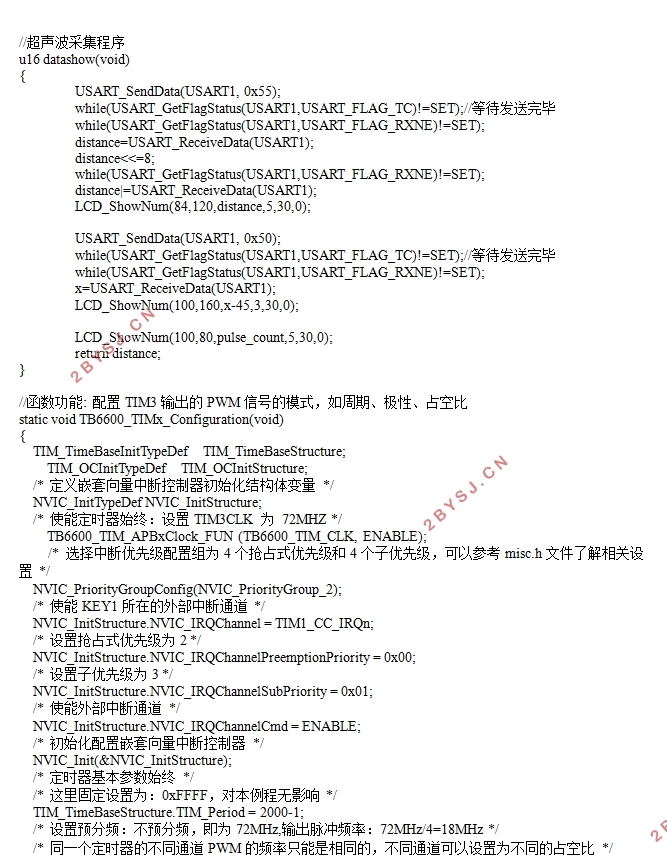
4.3.3 超声波传感器数据采集程序 17
4.3.4 串口通信程序 19
4.3.5 复位程序 20
第五章 系统调试 22
5.1 硬件平台的设计 22
5.1.1 器件选择和购买 22
5.1.2 硬件平台搭建 22
5.1.3 电路测试 23
5.2 系统调试 23
5.3系统调试结果 26
5.4 遇到的问题与解决方法 27
5.5 设计改进 28
结 语 29
参考文献 30
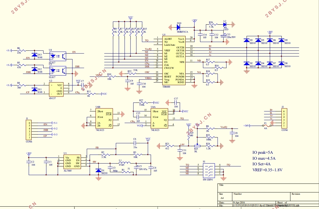
附 录1 电机驱动电路原理图 31
附 录2 部分代码 32
致 谢 34
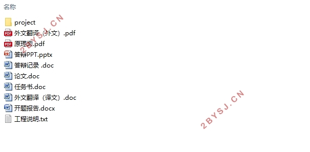
* 工程说明
*1、MCU:STM32F103VET6
*2、编程语言:C语言
*3、编译环境:Keil(uVision V4.54)
*4、固件库:3.5版本
*5、stm32demo.uvproj为keil的工程文件
编译步骤:
1.点击Target Options,点击Device选取MCU;
2.点击C\C++,在includes Path中填写所需编译文件的路径;
3.点击Debug,选择软硬件调试;
4.点击Utilities,选择Device size为512K;
5.最后点击Rebuild,编译工程。
工程编译完成如果没有错误,则点击Download,将程序烧写到单片机中
