直流无刷电机控制器的软件设计
无需注册登录,支付后按照提示操作即可获取该资料.
直流无刷电机控制器的软件设计(论文12000字)
摘要
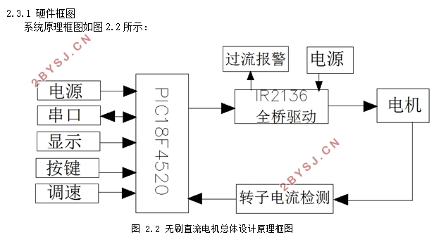
本文所论述的内容是以无刷直流电机(BLDC)控制器的软件(基于单片机)设计为背景,采用基于PIC18F4520的PIC单片机汇编语言,用MPLAB集成开发环境(IDE)编译软件,驱动芯片:IR2136,从而实现对无刷电机的正反转以及速度控制。采用比例积分微分(PID)控制器方式可以对无刷电机速度有更好的控制效果。比例积分(PI)调节器的比例(P)部分使动态响应比较快(无滞后),积分(I)部分使系统消除静差,通过PI调节器的调节作用使电动机的转速达到静态无差。本文分析了无刷直流电动机采用PWM控制稳定换相的过程,可以在换相时控制非换相相电流有稳定不变的幅度,并进行补偿以消除低速和高速工作下的换相转矩脉动。
关键词:无刷直流电动机(BLDC),比例积分微分(PID)控制器,PIC18F4520
Abstract
The content in this paper is based on single chip microcomputer motors design for the controller of brushless dc motor (BLDC) software.Using the PIC MCU assembly language based on PIC18F4520. With MPLAB integrated development environment (IDE) compile software.driving chip:IR2136 to make the brushless motor rotation. Adopting proportional integral differential (PID) controller can control the brushless motor speed better. The proportion part (P) of the proportional integral(PI) controller makes the dynamic response faster (with no lag). And the integral part (I) makes the system to eliminate static error. By regulating the function of PI regulator to make the speed of the motor without static error .The paper analyzes the steady commutation process of the BLDC motor using PWM mode,which can not only entirelyeliminate torque ripple resulted from the current emerging in the turn-off phase during non-commutation period but also compensate torque ripple caused by the commutation current during commutation period.
Keywords: Brushless DC motor(BLDC),Proportional Integral Derivative controller(PID),PIC18F4520
无刷直流电机的工作原理
无刷直流电机是由位置传感器(霍尔元件)输出位置信号,电子换相电路(全桥电路)根据位置传感器输出的位置信号驱动电枢线圈绕组对应的功率开关管,使各相绕组轮流通电,在电机定子上产生旋转的磁场驱动永磁转子旋转。位置传感器检测转子的位置输出具有周期性变化的电信号,驱动电路以位置信号为基准改变电枢绕组的通电状态。
本文所讨论的是三相星型链接的无刷直流电机。图1.3为全桥式无刷直流电机驱动电路,图中 V1,V2,V3,V4,V5,V6 为 MOSFET 功率管,高电平导通,低电平截止。


目 录
摘要 I
Abstract II
第一章 绪论 1
1.1课题背景 1
1.2无刷电机的历史与现状 1
1.2.1无刷电机在我国现状 2
1.2.2无刷电机的应用价值 2
1.2.3 无刷直流电机和有刷直流电机的比较 2
1.2.4 无刷直流电机的组成及结构 3
1.2.5 无刷直流电机的工作原理 4
第二章 硬件 8
2.1 单片机简介 8
2.1.1 产品特点 8
2.1.2 PIC18F4520概述 9
2.2 IR2136驱动芯片的特点 10
2.3硬件框图及I/O端口 10
2.3.1 硬件框图 10
2.3.2 芯片I/O接口 11
第三章 电机控制方法 12
3.1 PID控制原理 12
3.1.1PID工作原理 12
3.1.2 PID控制特点 12
3.1.3 PID优点 13
3.1.4位置式PID和增量式PID区别: 14
3.1.5比例、积分和微分控制 14
3.1.6 PID参数功能及作用 15
3.2 PWM原理及其调速作用 15
3.2.1 PWM理论基础 15
3.2.2 PWM调速 16
第四章 软件设计 18
4.1 MPLAB IDE 18
4.1.1 MPLAB IDE简介 18
4.1.2 MPLAB IDE功能 18
4.2 汇编语言 18
4.2.1汇编语言简介 18
4.2.2汇编特点 19
4.2.3 PIC汇编 19
4.3程序设计 20
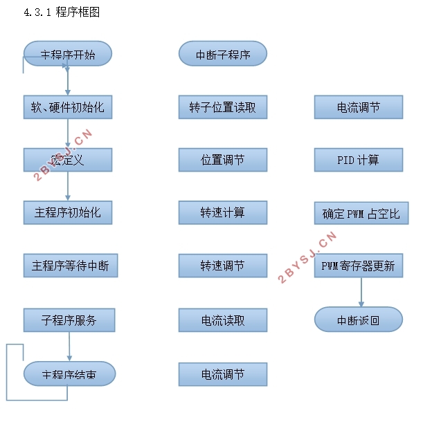
4.3.1 程序框图 20
4.3.2变量定义: 21
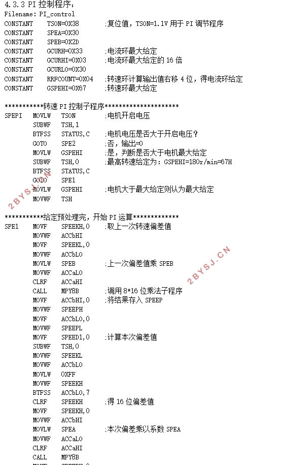
4.3.3 PI控制程序: 23
参考文献 27
致谢 28
