基于STM32的智能机器人小球控制系统设计
无需注册登录,支付后按照提示操作即可获取该资料.
基于STM32的智能机器人小球控制系统设计(任务书,开题报告,外文翻译,论文11200字)
摘要
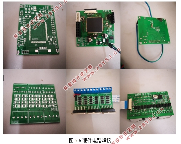
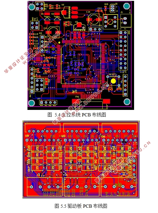
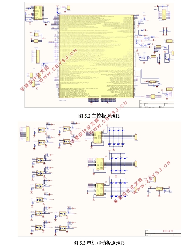
针对一种机器人小球,设计了基于STM32的控制系统。论文主要工作有:设计了控制系统的硬件电路,主要包括电源电路、复位电路、调试接口、电机驱动电路的设计。设计了控制系统软件,主要包括连接手机程序,接收手机数据程序和控制电机动作程序的下位机程序,以及移动控制终端的app程序。进一步,搭建了硬件电路的,实现软硬件的联合调试。结果表明:所设计的系统能顺利完成控制任务,达到了预期效果。
关键词:机器人小球,控制系统,STM32
Abstract
For a robotic ball, a control system based on STM32 is designed. The main work of the dissertation includes: designing the hardware circuit of the control system, including the design of power supply circuit, reset circuit, debug interface and motor drive circuit. The control system software is designed, which mainly includes connecting the mobile phone program, receiving the mobile phone data program and the lower machine program controlling the motor operation program, and the mobile control terminal app program. Further, a hardware circuit is built to implement joint debugging of hardware and software. The results show that the designed system can successfully complete the control task and achieve the expected results.
Keywords:Robot ball, control system, STM32
2.1系统设计要求
本次设计中,具体要求:
1. 针对已有的机器人小球结构,开发控制系统的硬件电路,要求包含电源模块,电机调速控制模块,视觉模块等。
2. 开发相应模块的驱动程序
3. 实现对小球机器人的无线控制。
2.2系统总体方案
系统拟实现功能:通过手机app实现对小球机器人运动速度和方向的控制,同时配备传感器获取小球运行时的相关信息。
根据机器人小球的控制目标对系统进行设计,可将控制系统分为五个模块:处理器模块,电源模块,传感器模块,电机模块,通信模块和上位机控制模块


目录
第1章绪论 1
1.1研究背景及意义 1
1.2国内外研究现状 1
1.2.1国内研究现状 1
1.2.2国外研究现状 2
1.3主要设计工作及章节安排 3
第2章系统总体设计 5
2.1 系统设计要求 5
2.2 系统总体方案 5
第3章系统硬件电路设计 7
3.1主控芯片及其外围电路设计 7
3.1.1 STM32最小系统设计 7
3.1.2系统供电电路设计 8
3.2 传感器模块 9
3.2.1 图像传感器模块 9
3.2.2 陀螺仪 10
3.3 电机控制模块 11
3.4 蓝牙通信模块 12
3.5 本章小结 13
第4章系统程序设计 14
4.1 总体方案设计 14
4.2下位机程序设计 15
4.2.1 HAL库初始化 15
4.2.2 时钟初始化 15
4.2.3 串口3初始化 16
4.2.4 定时器PWM输出初始化 17
4.2.5 蓝牙模块初始化 17
4.2.6 蓝牙数据处理函数 18
4.2.7 运动控制函数 18
4.3 上位机程序设计 19
4.3.1蓝牙控制实现 20
4.4 本章小结 20
第5章样机制备及实验 21
5.1 硬件制备 21
5.1.1 硬件开发环境 21
5.1.2 PCB设计 21
5.1.3 实物焊接 24
5.2 软件开发 24
5.2.1 下位机开发 24
5.2.2 下位机开发 25
5.3 实物调试 28
5.3.1 红外避障功能测试 28
5.3.2 蓝牙通信测试 29
5.3.3 app测试 30
第6章总结与展望 31
6.1 总结 31
6.2展望 31
参考文献 32
致谢 34
