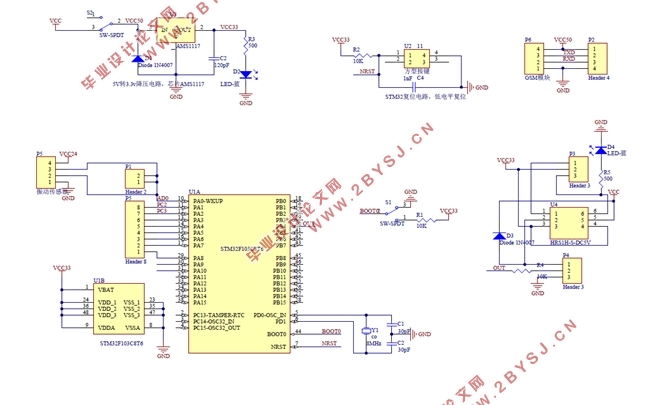
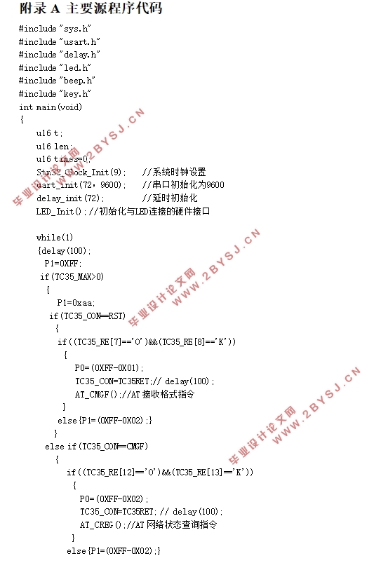
基于单片机的音叉物位开关的设计(附程序代码,电路原理图)
无需注册登录,支付后按照提示操作即可获取该资料.
基于单片机的音叉物位开关的设计(附程序代码,电路原理图)(任务书,开题报告,论文10000字)
摘 要
近些年来,数字技术快速发展,被普遍的应用在智能控制的领域中。单片机因为所占空间小、功能多、价格便宜、便于开发,受到了许多电子系统设计者的偏爱。本设计旨在设计出一种价格相对低廉,便于检测和控制的开关系统,同时在使用上便捷简单。本设计以单片机为基础的音叉物位开关控制系统,其核心是STM32F103C8T6单片机,报警系统由GSM模块完成,实现了对音叉物位开关工作过程的控制,包括物位接触音叉时开关断开,不接触时开关闭合和结束报警等几个阶段。控制系统的主要组成部分是三大模块,其中包括为单片机主控系统;供应3.3V的直流电压的是电源电路;由STM32F103C8T6单片机、LED指示灯构成的负责控制音叉开关的工作过程的单片机主控系统,以及由继电器、三极管、LED灯、GSM模块构成的外部硬件电路。本系统的电路比较简单,为STM32F103C8T6单片机载入软件程序后,能够实现音叉物位开关的基本功能。
关键词:继电器 控制系统 GSM模块
Design of Level Switch Based on Single Chip Microcomputer
Abstract
With the rapid development,digital technology is widely used in the field of intelligent control. Microcontrollers are favored by many electronic system designers because of their small footprint, more features, inexpensive and easy to develop. The design is designed to design a relatively low price, easy to detect and control the switching system, and simple to use . The design of the single-chip-based tuning fork level control system, the core is STM32F103C8T6 microcontroller, the alarm system by the GSM module to achieve the realization of the tuning fork level of the work of the control process, including the level of contact fork when the switch off , Do not touch the switch closed and the end of the alarm several stages. The main component of the control system is the three modules, which include the main control system for the microcontroller; supply 3.3V DC voltage is the power supply circuit; by the STM32F103C8T6 microcontroller, LED indicator is responsible for controlling the work of the tuning fork switch single-chip master System, and by the relay, transistor, LED lights, GSM module composed of external hardware circuit.The circuit of this system is relatively simple, STM32F103C8T6 single-chip load software program, to achieve the basic functions of tuning fork level switch.
Key Words: Relay;Control system;GSM module


目 录
摘 要 I
Abstract II
第一章 绪论 1
1.1 引言 1
1.2 音叉物位开关的现状 1
1.3 智能仪表的发展前景与趋势 2
1.4 设计任务与要求 2
1.5 论文结构 2
第二章 方案论证 4
2.1 MCU选择 4
2.2 震动传感器模块 5
2.3 RS-422接口 5
2.4 TC35短信模块简介 6
2.4.1 常用AT指令 7
2.4.2 PDU编码规则 8
2.5 系统总体设计思路 9
第三章 硬件设计 11
3.1 系统原理框图设计 11
3.2 系统主要元器件介绍 11
3.2.1 STM32F103C8T6主控芯片 11
3.2.2 AMS1117稳压器 14
3.2.3 HRS1H-S-DC5V 14
3.2.4 LM324 15
3.3 系统模块电路设计 15
3.3.1 STM32F103C8T6最小系统 15
3.3.2 TC35短消息模块接口电路 17
3.3.3 电源模块 18
3.4 硬件设计小结 19
第四章 软件设计 20
4.1 软件的程序实现 20
4.2 主程序算法流程分析 20
4.3 报警电路流程图 21
4.4 AD转换流程图 23
4.5 软件设计小结 24
第五章 系统调试 25
5.1 程序生成及系统仿真 25
5.2 系统制作及实物测试 27
结 语 29
致 谢 30
参考文献 31
附录A 主要源程序代码 33
附录B 电路总体原理 38
