基于单片机交通灯的设计(含电路原理图,PCB图,程序)
无需注册登录,支付后按照提示操作即可获取该资料.
基于单片机交通灯的设计(含电路原理图,PCB图,程序)(论文18000字)
摘 要
根据STC10F04单片机的特点及交通灯在实际控制中的特点,本文提出一种用单片机自动控制交通灯及时间显示的方法。同时给出了软硬件设计方法,设计过程包括硬件电路设计和程序设计两大步骤,对在单片机应用中可能遇到的重要设计问题都有涉足。本文对十字路口状态预设为三种,一种是正常状态,一种是紧急状态,另一种是方程式状态。增设路段遇忙调整时方程式控制状态和紧急情况处理模块,通过手动控制开关按钮A0和A1方便系统在正常状态和紧急状态、方程式控制间来回切换,进一步完善了交通灯控制系统。并分别用红、黄、绿灯的不同组合来指挥两个方向通车与禁行,用LED数码管作为倒计时指示,实时的控制当前交通灯时间使LED显示器进行倒计时工作并与状态灯保持同步,在保持交通安全的同时最大限度的提高交通能顺畅交替运行。本文介绍了控制基本原理以及控制的表现,同时,论述了系统中交通现状、交通管理、交通规则及背景信息。
关键词:自动控制,时间显示器,外部中断,延时,方程式控制
Abstract
According to the characteristics of single-chip STC10F04 and traffic lights in the actual control of the characteristics of this paper, a single-chip automatic control with traffic lights and the method of time display. At the same time, given the hardware and software design methodology, design process, including the hardware circuit design and program design two major steps in the single-chip applications that may be encountered in the design of the important issues are involved. In this paper, the default state of the crossroads for three, one is the normal state is a state of emergency, and the other is a state formula. Additional sections of busy status adjustment formula and an emergency control module Through the manual control switch button convenience A0 and A1 system in the normal state and a state of emergency, the equation between the control switch back and forth, and further improve the traffic light control system. And were red, yellow and green light to direct different combinations of traffic in both directions and cut-line, with LED digital tube as a countdown to the instructions, real-time control of the current time for traffic lights to LED countdown display work and to keep pace with the state of light in the to maintain safety while minimizing the increase in traffic to alternate running smoothly. This paper introduces the basic principles of control, as well as the performance of control at the same time, traffic on the system status, traffic management, traffic regulations and background information.
Key words: automatic control; time display; external interrupt; delay; control equation
交通灯的工作原理
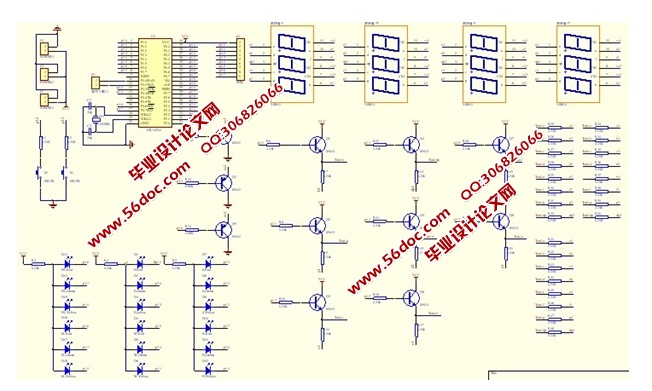
采用单片机的I/O口P1、P2和P3.6、P3.7直接和交通灯连接,P0、P4口通过限流电阻和三极管接LED数码管。控制程序放在STC10F04单片机的ROM中,在十字路口的四组红、黄、绿交通灯中,由单片机P1.0-P1.7,P2.0-P2.7和P3.6、P3.7控制,由于交通灯为发光二极管且阳极通过限流电阻和电源正极连接,因此I/O口输出低电平时,与之相连的相应指示灯会亮,并通过LED数码管显示时间倒计时。I/O输出高电平时,相应指示灯会灭。紧急车请求通过的信号由人工控制,以中断方式输入单片机,无紧急车通过时,中断引脚INT0(P3.2)通过电阻和电源正极连接为高电平,不产生中断,单片机执行主程序,有紧急车通过时,中断引脚INT0(P3.2)采用人工方法接地为低电平,产生中断请求,单片机执行中断服务程序,让紧急车通过,紧急车通过后,中断引脚INT0(P3.2)变为高电平,返回主程序。方程式控制通过的信号由人工控制,以中断方式输入单片机,不需调整周期时,中断引脚INT1(P3.3)通过电阻和电源正极连接为高电平,不产生中断请求,单片机执行主程序,当车辆多需要增加主干道通车时间时,中断引脚INT1(P3.3)采用人工方法接地为低电平,产生中断请求,单片机执行中断服务程序,系统以方程式控制,按一次开关按钮A1执行方程式A,按两次开关按钮A1时执行方程式B,按三次开关按钮A1时执行方程式C。当按四次时,中断引脚为高电平,返回主程序。


目 录
摘 要 1
Abstract 2
目 录 3
1 绪论 4
1.1 交通灯研究的背景和意义 4
1.2 交通灯国内外发展概况 4
2 系统工作原理及设计方案 7
2.1 交通灯的工作原理 7
2.2 交通灯总体设计方案 7
3 硬件系统设计 11
3.1 硬件系统组成 11
3.1.1 单片机最小系统 11
3.1.2 信号显示驱动电路 15
3.1.3 键盘输入电路 16
4 交通灯系统详细设计 18
4.1 软件总体设计思想 18
4.2 交通控制算法实现 20
4.3 系统初始化模块 21
4.4信息显示模块 22
4.4.1 信号灯模块 22
4.4.2 LED倒计时显示子程序 26
4.5键盘扫描模块 29
5 调式总结 37
6 致 谢 38
参考文献 39
附 录 40
附录一 程序清单 40
附录二 交通灯PCB图 48
附录三 交通灯电路原理图 49
