基于AT89S52单片机电子日历设计(含电路图,原理图,程序)
无需注册登录,支付后按照提示操作即可获取该资料.
基于AT89S52单片机电子日历设计(含电路图,原理图,程序)(任务书,外文翻译,毕业论文10000字,CAD图4张)
摘要
设计以单片机AT89S52为核心部件的电子日历,利用74LS07作为驱动器,74LS164作为移位寄存器,六个七段数码管均采用共阳极的方式,P0口作为段选码输出口,P2口作为位选码输出口。
本次设计的题目是基于单片机的电子日历设计,可以正常的显示年、月、日、时、分、秒等功能。电子日历具有性能稳定、精确度高、成本低、易于产品化,以及方便、实用等特点。适用于家庭、公司、机关等众多场所。为人们的日常生活、出行安排提供了方便,成为人们日常生活中不可缺少的一部分。
本次设计可分为两部分:硬件系统、软件系统。
硬件系统包括:AT89S52单片机、74LS07驱动器、74LS164移位寄存器、RC复位电路、+5V直流电源电路、去抖电路、动态显示扫描电路。
软件系统主要用汇编语言编制,实现显示,计算等功能。
关键词:单片机1,AT89S52,74LS07,74LS164,
AT89S52 Microcontroller based Design of electronic calendar
ABSTRACT
AT89S52 MCU as the core design components of the electronic calendar, use as a driver 74LS07, 74LS164 as a shift register, the six seven-segment digital tube all the way with common cathode, P0 port as the output section of the election code, P2 mouth as a bit selection code output.
This design is the subject of electronic calendars based on single chip design, so it can display year, month, day, hour, minute, second and so on. Electronic calendar with stable performance, high accuracy, low cost, easy-to-product technology, as well as convenient, practical and so on. Apply to families, companies, agencies and many other places. For people's daily lives, providing a convenient travel arrangements, become an indispensable part of daily life.
This design can be divided into two parts: hardware and software in the system.
Hardware system includes: AT89S52 microcontroller, 74LS07 drive, 74LS164 shift register, RC reset circuit, +5 V DC power supply circuit, to shake circuit, dynamic display scanning circuit.
MCU main software system programming form.
KEY WORDS: microcontrolle ,AT89S52 ,74LS07 ,74LS164,
目 录
前 言 1
第1章 项目设计要求 2
1.1 毕业设计及要求 2
1.1.1 设计任务要求 2
1.1.2 技术指标 2
1.1.3 系统掌握 2
第2章 芯片介绍 4
2.1 AT89S52介绍 4
2.1.1 AT89S52性能介绍 4
2.1.2 AT89S52结构引脚 6
2.2 74LS164介绍 6
2.2.1 74LS164 6
第3章 系统设计 8
3.1 系统确定 8
3.1.1 框架设计 8
3.2单片机最小系统应用 8
3.2.1 单片机的时钟电路 9
3.2.2 复位电路和复位状态 10
第4章 硬件设计 14
4.1 电路原理图 14
4.1.1 工作原理 14
4.1.2 元件清单 14
4.2 LED显示设计 15
4.2.1 LED数码管 15
4.2.2 LED数码管编码方式 16
4.2.3 LED数码管显示方式和典型应用电路 17
第5章 软件设计 19
5.1软件设计 19
5.1.1 程序流程图 20
5.1.2 程序清单 20
结 论 32
谢 辞 33
参考文献 34
附 录 36
外文资料翻译 37
附 录
附录题目
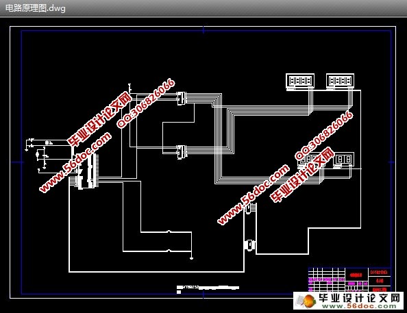
附图1 电路原理图。
附图2 流程图框架图
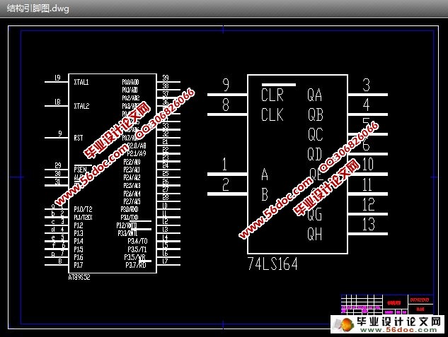
附图3 结构引脚图。
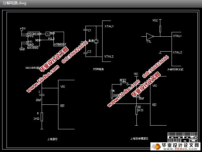
附图4 分解电路。
