基于单片机控制的交通灯设计(附程序,电路图)
无需注册登录,支付后按照提示操作即可获取该资料.
基于单片机控制的交通灯设计(附程序,电路图)(论文6600字)
摘 要
十字路口车辆穿梭,行人熙攘,车行车道,人行人道,有条不紊。那么靠什么来实现这井然秩序呢?靠的是交通信号灯的自动指挥系统。交通信号灯控制方式很多。本设计主要分为五大模块输入控制电路、时钟控制电路、片内外程序切换控制、显示电路。以MSC-51系列单片机IntelAT89C51为中心器件来设计交通灯控制器,实现了AT89C51芯片的P0口设置红、绿灯、黄灯燃亮时间的功能;为了系统稳定可靠采用了74LS14施密特触发器芯片的消抖电路,避免了系统因输入信号抖动产生误操作;显示时间直接通过AT89C51的P2口输出,由CD4511驱动LED数码管显示红灯燃亮时间。
关键字:AT89C51 LED显示 交通灯
the traffic light based on the single-chip control
Abstract
The intersections vehicle wears shuttle, pedestrian Xi Rang, garage driveway, person's sidewalk, orderly. So depend what to carry out this well arranged order? What to depend is a traffic sign light of automatic conductor system. The control method of the traffic sign light is a lot of. This design is mainly divided into five greatest molds a piece the electric circuit, clock of the importation control a control outside procedure inside the electric circuit, slice to cut over a control and shows electric circuit. Take single slice the machine IntelAT89 C51 of the serieses MSC-51s as a center spare part to design transportation light controller, carried out the AT89 C51's P's 0 people's constitution of the chips red, the function in bright time of green light, Huang2 Deng Ran2;For the sake of system stability the credibility adopted a 74 LS14 airtight trigger eliminate of machine chip to tremble electric circuit especially, avoided system because of importation the signal tremble movable property to living a mistake operation; The P 2 people who shows that time directly passes the AT89 C51 output, is driven LED figures a tube by the CD4511 to show red-light Ran bright time.
Key word: The AT89 C51 LED show transportation light


目 录
摘 要 2
ABSTRACT 3
前 言 4
一、工程简介 5
(一)、概述 5
(二)、工艺流程图 5
二、工程设计 6
(一)、控制方案的确定 6
(二)、硬件部分 7
(1)、交通灯控制系统的硬件设计 7
(2)、硬件系统的设计具备以下原则 7
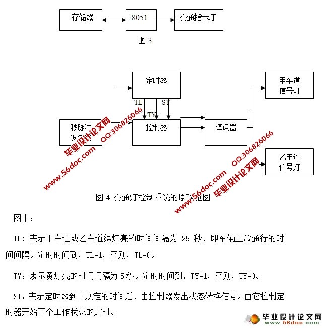
(3)、硬件结构框图(如图3所示) 7
(4)、交通灯控制系统的原理框图(如图4所示) 7
(5)、8279的结构及引脚功能 12
(三)、软件部分 13
(1)、延时子程序的计算 13
(2)、流程图(如图8所示) 13
三、系统的试调运行 15
(一)、硬件调试 15
(1)、静态调试 15
(2)、动态调试 15
四、系统设计及总结特点 16
致 谢 17
参考文献 17
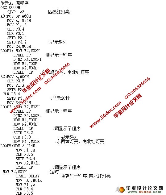
附录A:源程序 18
附录B:电路图 23
