基于单片机控制的智能充电器设计(含电路图,Proteus仿真程序)
无需注册登录,支付后按照提示操作即可获取该资料.
基于单片机控制的智能充电器设计(含电路图,Proteus仿真程序)(任务书,论文11800字,Proteus仿真程序)
摘 要
在能源面临危机的今天,绿色环保新能源受到全世界各国的关注的同时,也得到了大规模的应用。电动车出现为能源危机的解决和大气环境污染治理,提供了良好解决途径。作为电动车重要组成部分,如何研制性能良好的智能充电器,对电动车的行业发展具有重要的意义。
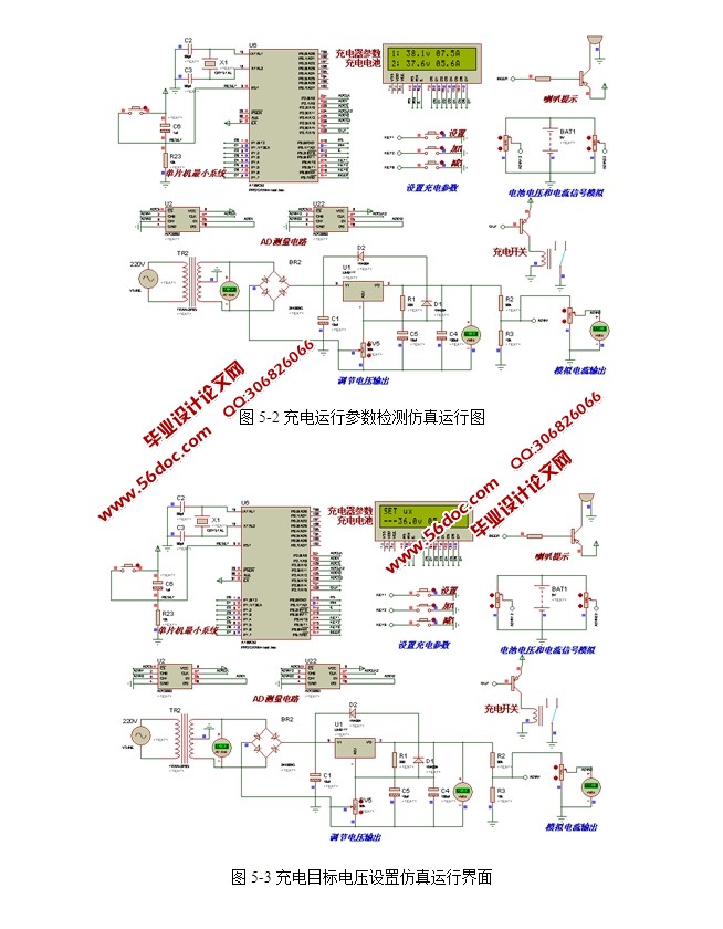
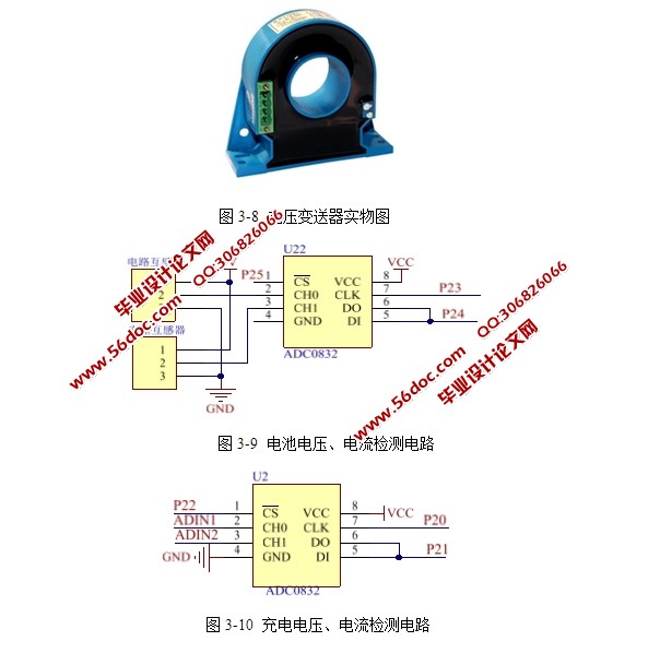
本文利用STC89S52单片机设计一款智能充电器的控制系统,通过对电压传感器和电流传感器的检测,当检测充电电压和电流大设置值时,自动断开充电电路。本设计由软件和硬件两部分组成,硬件设计对单片机最小系统、电压电流采集电路、充电控制电路、按键电路、液晶显示电路、报警电路等进行设计,使控制器具备电压、电流检测,系统参数显示,自动断电控制等功能;软件设计方面对控制器的软件驱动程序进行设计。并利用Protues软件进行可行性仿真,对软件和硬件设计进行验证。
关键词:控制器;充电器;蓄电池
Abstract
In the energy crisis today, the new green energy, environmental protection and new energy by the attention of countries all over the world at the same time, has also been a large-scale application. Electric vehicle energy crisis resolution and atmospheric pollution control to provide a better solution. As an important part of the electric car, how to develop the good performance of the intelligent charger, to the electric car industry development has important significance.
The STC89C52 control system design of a intelligent charger, detection of current and voltage sensor, when detecting the charging voltage and high current setting value, automatically disconnect the charging circuit. The design consists of two parts, hardware and software, the hardware design of the smallest single-chip system, voltage and current sampling circuit, charging control circuit, key circuit, LCD display circuit, alarm circuit design, the controller with voltage, current detection, system parameters show that automatic power-off control; software design of the controller software driver design. And the Protues software for feasibility simulation, software and hardware design verification.
Key words: controller; charger; battery
2.1设计目标
1)实现对36V蓄电池的充电。
2)实现对充电电压、电流和电池电压和电流的检测功能。
3)实时显示充电压、电流和电池电压、电池的实时显示。
4)实现智能充电器的软件和硬件电路设计。
5)对智能充电器进行原理仿真,对软件和硬件设计进行验证。
2.2设计思想
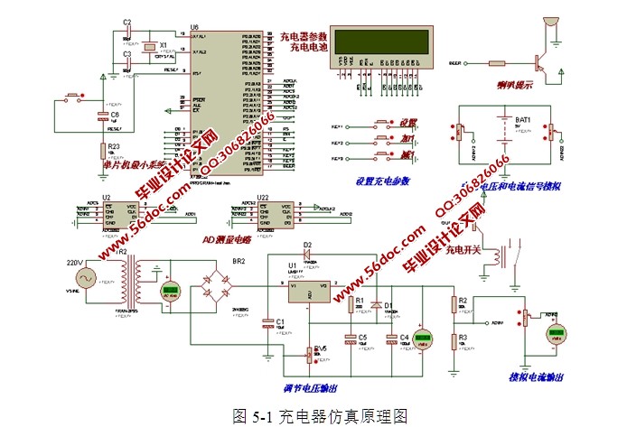
根据系统目标可知,系统需要实现输入的采集功能(按键、充电电压、充电电流、蓄电池电压和蓄电池电流的采集)和输出(液晶显示、蜂鸣器报警)的控制功能。通过对整体设计目标进行评估设计中选择单片机作为核心的控制芯片,通过扩展电压、电流采集电路、蜂鸣器报警电路、液晶显示电路、按键电路等接口电路实现系统硬件设计。通过软件编程控制各个功能模块协调工作,完成智能充电器的设计要求[4-7]。
2.2.1硬件实现原理
硬件设计需要搭建输入的采集和输出端的受制的平台。首先设计根据输入量和输出的特点,选择相应的器件进行电路原理设计,根据设计原理图购买相应的器件,搭建系统硬件平台,并对硬件平台进行调试,为软件控制提供一个良好的运行平台。


目 录
一、绪论 1
1.1 选题背景及意义 1
1.2国内研究现状 1
1.电池技术得发展 1
2.充电技术的发展 1
1.3研究的内容及结构安排 2
二、系统设计方案分析 3
2.1设计目标 3
2.2设计思想 3
2.2.1硬件实现原理 3
2.2.2软件实现原理 3
2.3主要器件选型 4
2.3.1主控器选型 4
2.3.2按键模块选择 5
2.3.3显示电路选择 5
2.3.4报警模块选择 5
2.3.5供电方式选择 6
2.3.6传感器选型 6
2.4 系统总体框架 6
三、 系统硬件设计 8
3.1单片机最小系统 8
3.1.1 单片机最小系统 8
3.2 充电控制电路 10
3.3显示电路设计 11
3.4按键电路设计 11
3.5充电控制电路设计 11
3.6报警电路设计 12
3.7传感器采集电路设计 13
3.7.1电流变送器介绍 13
3.7.2传感器采集电路设计 14
四、系统软件设计 15
4.1主程序设计 15
4.2充电界面显示子程序设计 16
4.2设置目标充电电压程序 16
4.3设置目标充电电流程序 17
五、系统仿真 18
5.1仿真软件介绍 18
5.2仿真建立步骤 18
5.3仿真原理图设计 18
5.4仿真原理介绍 19
5.5仿真运行结果分析 20
总结 21
致 谢 22
参考文献 23
