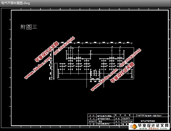
某市110KV变电站一次部分设计(含CAD接线图,电气平面布置图)
无需注册登录,支付后按照提示操作即可获取该资料.
某市110KV变电站一次部分设计(含接线图,电气平面布置图)(任务书,开题报告,中期检查表,毕业论文22000字,CAD图3张)
摘 要
本文首先根据任务书上所给系统与线路及所有负荷的参数,并通过对负荷资料的分析,从安全,经济及可靠性方面考虑,确定了110KV、35KV、10kV以及站用电的主接线,然后又通过负荷计算及供电范围确定了主变压器台数,容量及型号,同时也确定了站用变压器的容量及型号,其次,对高压熔断器,隔离开关,母线,电压互感器,电流互感器等进行了选型和校验,并依据继电保护配置原理,对所选择的保护进行整定和灵敏性校验,确定方案中的保护。其中变压器保护包括保护原理分析,主保护采用的是纵联差动保护和瓦斯保护,两者结合做到优势互补,后备保护是复合电压启动过电流保护。母线保护包括保护原理分析,采用了完全电流差动保护,简单可靠。最后,对变电站进行防雷保护设计,从而完成了110kV电气一次部分的设计。
关键词:变电站 变压器 主接线 短路电流计算 继电保护
Abstract
The This text the first according to the system and the circuits and all the parameters of the burdens that the mission in the book give, and pass to the consider towards carrying the data analytical, safety, the economic and the dependable sex aspect, made sure the 110 KV, 35KV,10 KV and the stood to use the electricity of lord connect line, then again made sure the main transformer set through the burden calculation and the power supply scopes number, capacity and model number, also made sure that the station uses the capacity and model numbers of the transformer, the next in order, break the machine to the high pressure , insulate the switch, female line, electric voltage with each other the feeling machine, electric current with each other the feeling machine etc. carries to choose the type and schools to check, Among them transformer protection include protection principle analysis, protection complete calculate and delicate extent checkout, central protection is lengthways associated differential protection and gas protection, both combine to attain advantage to with each other repair, spare protection is compound electric voltage start conduct electricity to flow protection. generatrix line protection include protection principle analysis, adoption complete differential electric current protection, simple credibility.,end, carried on to the main transformer and transformer substation after the electricity protection design, thus completed the 110 kV electricity once part of design.
Keyword: Transformer substation, transformer, the lord connects the line, short-circuit electric current calculation,relay protection。
1.1设计依据
根据省电力公司XX号文件,关于ZY变电所设计任务书的规定。
1.2建站的必要性
ZY市是一个新兴的城市,其工业发展相当迅速,原系统的电力供给已不能满足经济发展的需求。为此,急需建立新的变电站以适应新的经济形势。建成的变电所将满足市区工业、生活及郊区乡镇工业与农业用户的用电需要。
1.3 规模设计
设计的变电所为110KV变电所,由3个电压等级110/35/10KV,分两期完成工程;
进出线回路数:110KV,近期2回,远景2回;
35KV,近期5回,远景2回;
10KV,近期12回,远景2回。
变电站电气一次部分的设计主要包含:负荷的分析计算、变压器的选型、主接线的设计、无功补偿、短路电流的计算、电气设备的选型和校验、母线的选择和校验等有关知识以及继电保护。


目录
摘 要………………………………………………………………………………A
Abstract……………………………………………………………………………B
第一章 变电站总体分析…………………………………………………………1
1.1设计依据…………………………………………………………………………1
1.2建站的必要性……………………………………………………………………1
1.3规模设计…………………………………………………………………………1
1.4所设计变电站的总体分析………………………………………………………1
第二章 负荷计算…………………………………………………………………2
2.1原始资料分析……………………………………………………………………2
2.2负荷计算的方法……………………………………………………………………………2
2.3负荷计算……………………………………………………………………………………2
第三章 主接线设计………………………………………………………………4
3.1 主变的选择………………………………………………………………………4
3.2 主接线设计………………………………………………………………………7
3.3 变压器中性点接地方式和中性点设计………………………………………11
3.4 无功补偿………………………………………………………………………12
第四章 配电装置平面的设计…………………………………………………16
4.1各种配电装置的特点…………………………………………………………16
4.2配电装置的型式选择…………………………………………………………16
第五章 短路电流的计算………………………………………………………18
5.1 短路计算的目的………………………………………………………………………18
5.2 任务………………………………………………………………………………………18
5.3基本假设…………………………………………………………………………………18
5.4 短路电流计算的一般要求……………………………………………………………18
5.5 参数计算…………………………………………………………………………………19
第六章 电气选择及校验………………………………………………………………23
6.1 电气设备选择的主要任务……………………………………………………………23
6.2 选择导体和电器的一般原则………………………………………………………23
6.3 选择导体和电器的技术条件………………………………………………………23
6.4选择结果………………………………………………………………26
第七章 继电保护……………………………………………………………………29
7.1 继电保护配置………………………………………………………………29
7.2 母线的保护配置………………………………………………………31
7.3 输电线路保护配置…………………………………………………31
7.4变压器成套自动保护装置…………………………………………………32
7.5母线成套自动保护装置…………………………………………………32
7.6输电线路成套自动保护装置…………………………………………………34
第八章 避雷保护…………………………………………………………………………35
8.1雷害的主要来源………………………………………………………………………35
8.2防雷设计的原则………………………………………………………………………35
8.3避雷针保护应注意的问题……………………………………………………………36
8.4防雷电波设计和防雷计算…………………………………………………………38
致 谢…………………………………………………………………………………………41
参考文献……………………………………………………………………………………42
附 录 一 负荷计算表
附 录 二 电气主接线图
附 录 三 电气总平面布置图
附 录 四 配电装置平面布置图
附 录 五 主变间隔断面图
