广州市17600平米服务中心工程空调通风设计(含CAD图)
无需注册登录,支付后按照提示操作即可获取该资料.
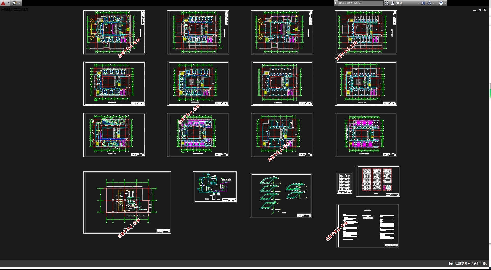
广州市17600平米服务中心工程空调通风设计(含CAD图)(任务书,开题报告,外文翻译,论文计算书34000字,CAD图15张)
摘 要
本设计为广州某服务中心空调系统设计,旨在为大楼活动人员提供一个舒适的室内热湿环境。
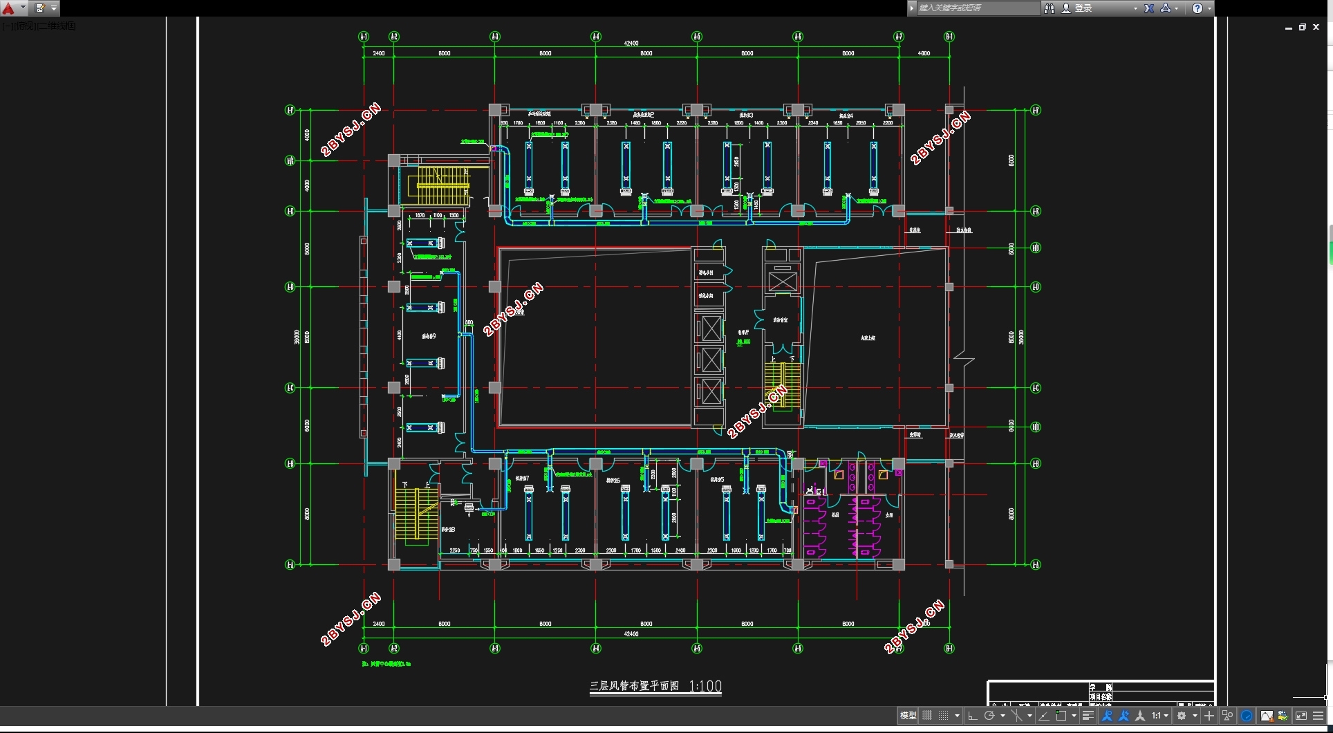
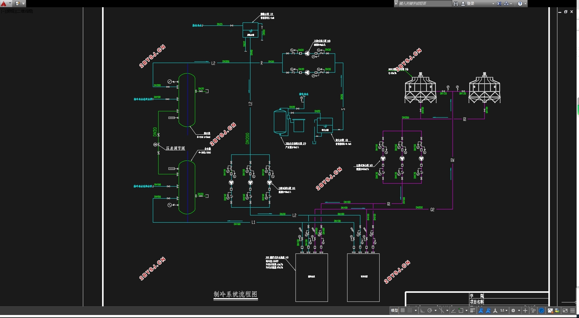
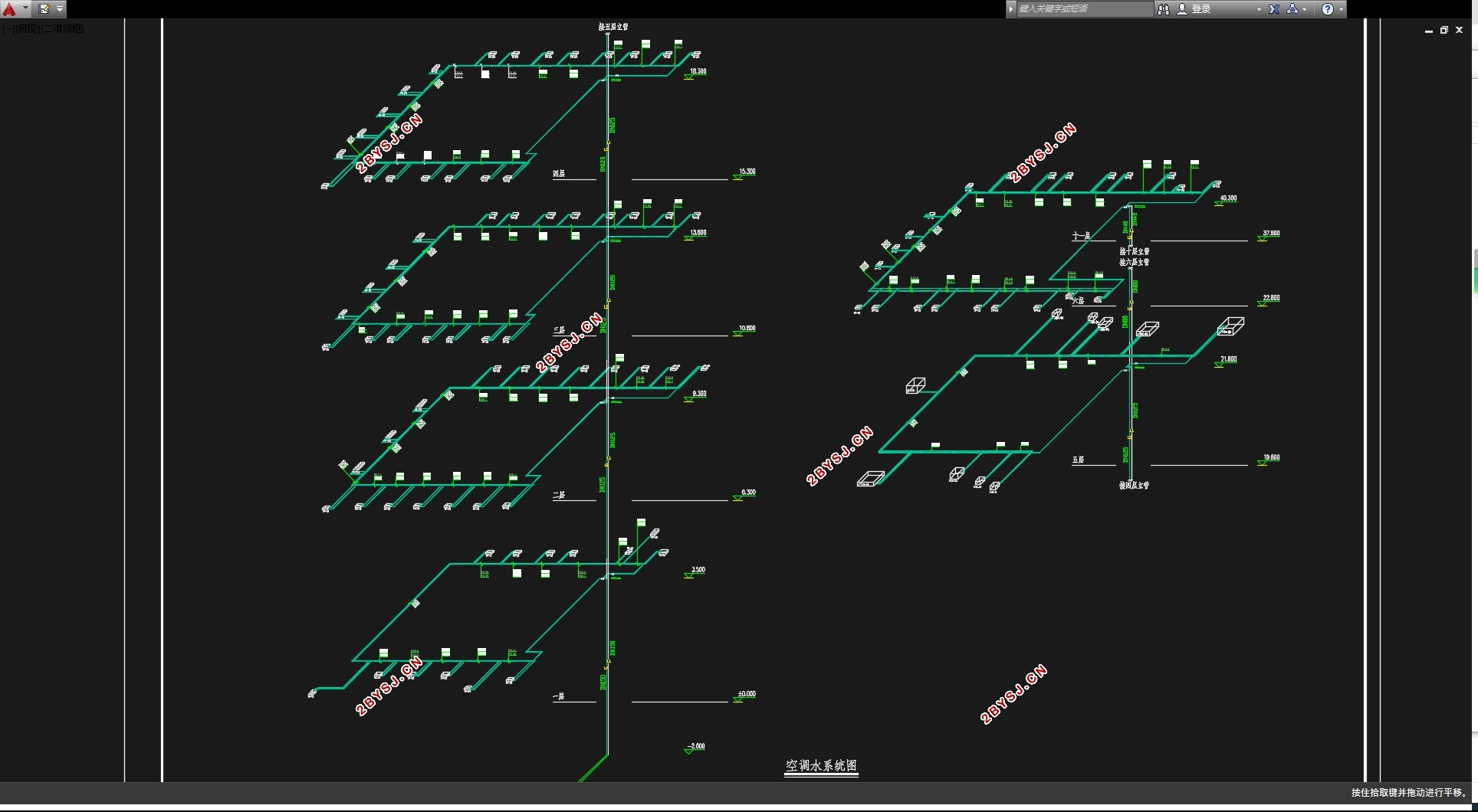
冷负荷计算采用非稳态方法,计算出7:00~19:00的逐时冷负荷,综合得夏季冷负荷为474kW。一层大堂采用全空气系统分层空调,空间较高,以空调区冷负荷计算,可达到节能的目的。其他各房间采用风机盘管加新风系统,新风处理到室内焓值,送入室内,不承担室内负荷。一层至四层房间气流组织选择散流器上送上回的方式,六至十一层各房间的气流组织选择侧送风的送风方式。空调水系统选择闭式、同程式、一次泵系统。本建筑位于广州市,属于夏热冬暖地区,夏季需制冷而冬季不需要供热,因此冷热源形式选择水冷式冷水机组加冷却塔的制冷方式。
关键词:冷负荷 全空气系统 风机盘管加新风系统 气流组织 冷水机组
Air conditioning and ventilation design of Guangzhou Service Center
Abstract
Design of air conditioning system for Guangzhou Logistics Service Center,The aim is to provide a comfortable indoor thermal and humid environment for building personnel。Cold load calculation using the non steady state method, the calculation of 7:00 ~ 19:00 hourly cooling load, Comprehensive summer cooling load is 474 kW.The first layer of air system is used in a layer of air conditioning system. The space is high, and the calculation of the cooling load of the air conditioning area can achieve the purpose of energy saving.Each room adopts fan-coil unit plus fresh air system, fresh air treatment to the indoor enthalpy value, acess to the room, do not assume the indoor load. One to four storey airflow in the room the choice of bulk flow is sent back to the way, six to eleven layer of each room airflow organization choice side air supply mode.Air conditioning water system select closed, a pump system.The building is located in Guangzhou City, belongs to the region of hot in summer and warm in winter, summer cooling and winter heating needs, so cold and heat source form selection of water-cooled chiller and cooling tower cooling.
Key Words: Cold load;All air system;Fan coil units and fresh air system;Air flow organization;water chilling unit
1.1 建筑概况
本建筑为广州市某服务中心(A区),总建筑面积17600m2 ,高度40.8m。A区地下一层,地上十一层,内设咖啡吧、包间、棋牌室、娱乐室、健身房、会议室、多功能厅、标准客房等功能房间。设计内容包括:(1)各功能房间的集中空调设计;(2)卫生间、变配电室、水泵房及地下层车库的通风设计。
1.2 原始资料
表1.2-1 围护结构参数
结构类型 类型 传热系数K(w/m2) 衰减系数β 延迟时间ξ 热惰性D 标准规定
外墙 外墙300mm厚,04级加气混凝土砌块框架填充墙; 0.59 0.31 11 4.57 查《实用供热空调设计手册》
屋面 80mm厚钢筋混凝土层,保温层,防水层架空屋面聚苯板材料; 0.44 0.15 12 4.18 查《实用供热空调设计手册》
外窗 6mm厚空气夹层玻璃 2.8 - - - 查《实用供热空调设计手册》
内墙 内墙200mm厚,加气混凝土空心砌块墙; 1.89 0.46 7 1.7 查《实用供热空调设计手册》
楼板 15mm厚聚苯颗粒浆料层间楼板1.4≤Vf≤2.2 1.89 0.43 5 1.58 查《实用供热空调设计手册》
由外窗传热系数,查附录[1]表3.3.1-5可得窗墙比为0.3-0.4,取0.35。


目录
摘 要 I
Abstract II
第一章 设计概况 1
1.1 建筑概况 1
1.2 原始资料 1
1.3 室内外设计参数 3
第二章 负荷计算 4
2.1 冷负荷计算 4
2.1.1 外墙和屋顶冷负荷 4
2.1.2 外窗冷负荷 6
2.1.3 室内热源散热形成的冷负荷 7
2.1.4 第11层9号客房冷负荷汇总 10
2.2 冷负荷总计 11
第三章 空调方案论证 12
3.1 空调系统方案的确定 12
3.2 风机盘管的结构和工作原理 12
3.3 风机盘管机组的新风供给方式和新风处理方案 13
3.3.1 新风供给方式 13
第四章 空调风系统送风量计算 14
4.1 系统划分 14
4.2 风机盘管加新风机组系统方案分析 15
4.3 全空气一次回风系统方案分析 16
4.4 全空气一次回风系统送风量及冷量计算 17
4.5 风机盘管加新风机系统送风量及冷量计算 19
4.6 组合式空气调节机组选型 22
4.7 风机盘管选型 22
4.8 新风机组选型 24
第五章 空调风系统设计计算 26
5.1 气流组织的基本要求 26
5.2 空调房间的气流组织 27
5.3 气流组织计算 27
5.3.1 全空气系统散流器送风房间 27
5.3.2 风机盘管散流器上送风房间 29
5.3.3 风机盘管侧送风房间 30
5.4 风管的水力计算 34
5.4.1风管水力计算的步骤 34
5.4.2全空气系统风管水力计算 34
第六章 空调水系统设计计算 37
6.1 水系统的设计 37
6.2 水系统的水力计算 37
6.2.1 水管水力计算的步骤 37
6.2.2 水管水力计算 37
6.3 冷凝水管的设计计算 40
第七章 冷热源方案及设备的选择 42
7.1 冷热源的选择 42
7.2 制冷机房设备计算及选型 46
7.2.1冷冻水泵的选择计算 46
7.2.2冷却水泵的选择计算 49
7.3 补水系统的设计 51
7.3.1补水泵的选择计算 52
7.3.2膨胀水箱的选择 53
7.3.3 软化水器的选择 54
7.3.4 软化水箱的选择 54
7.4 水系统的附件、设备及配管 55
7.4.1 分集水器的设计计算 55
7.4.2 水过滤器 56
7.5 冷却塔的选择 56
第八章 管道保温 59
8.1 保冷设计基本原则 59
8.2 保冷材料选择 60
8.3 保冷层厚度 60
参考文献 61
附表 62
