陕西大理河88m跨铁路桥(系杆拱桥)设计(含CAD图,Midas建模)
无需注册登录,支付后按照提示操作即可获取该资料.
陕西大理河88m跨铁路桥(系杆拱桥)设计(含CAD图,Midas建模)(任务书,开题报告,外文翻译,计算说明书13800字,CAD图13张,Midas建模)
摘要
系杆拱桥作为一种具有优美外形同时又适合在城市或者软土地基上修建的桥型,在国内外桥梁建筑史上都占有十分重要的地位,其施工方法和设计理论都已经比较成熟和完善。但是随着现在社会的飞速发展,新型材料、新型施工方法层出不穷,车辆的流量和载重也不断增大,这些都对系杆拱桥的进一步发展提出了新的挑战。而且系杆拱桥作为一种拱、梁组合的超静定结构体系,结构内力分析的过程较一般桥梁体系复杂,特别是拱、梁结合处多向受力状况的分析难度更大,所以对系杆拱桥的结构受力特性进行进一步地理论分析也就显得十分迫切和必要了。论文以对苗家坝大理河88m跨铁路桥为研究背景,运用平面和空间的有限元程序,对系杆拱桥整体结构在施工阶段和运营阶段的受力特性,以及拱、梁体系结合点处的局部受力状况,进行一些详细的理论分析,并用现有的规范标准进行论证,以期对该桥的施工控制和节点模型试验的设计提供一些必须的理论数据。
关键词:系杆拱桥;受力分析;有限元法
Abstract
Tied arch bridge is a bridge that has the outline of concinnity and is fit for building in the city or on the soft clay ground ,which possesses the important status in the domestic and foreign history of bridge building. Its construction method and design theory are already comparatively mature and perfect .But,with the quick development of the modern society,new materials and construction method are more and more ,the traffic of flux and vehicle’s load constantly go up .These new situations challenge the tied arch bridge’s more development. Moreover,the tied arch bridge’s structural analysis of internal force is more difficult than normal bridge system because it is a over-stable structural system that is composed of arch and beam. Specially,the combination of arch and beam receives many forces from many directions and is more difficulty analyzed .So, it is necessary and exigent to more study the tied arch bridge’s structural analysis of internal force.This paper is based upon 88-meter railway bridge of MiaoJia Ba of River Da Li .Through the plane and special finite element program ,this thesis take some particular theory
analysis about the construction and business phase and the local mechanics of the combination of arch and beam .Then ,it demonstrates these analysis according to the present criterion. At last ,it is expected to offer some necessary theory data for the bridge’s construction control and the design of node model experimentation.
Key words:tied arch bridge ; analysis of mechanics capability ; finite element method .
.1.3主要技术标准和设计基础资料
1.铁路等级:国铁I级;桥梁设计荷载:中-活载;设计时速:160km/h,预留200km/h;
2.桥梁净空及其它要求:①桥梁单向标准宽度为 16m;②桥上净空高度为 5m;
③桥下净空高度>7m;④设轨道双线;⑤纵坡:<1.3%;限坡:0.6%
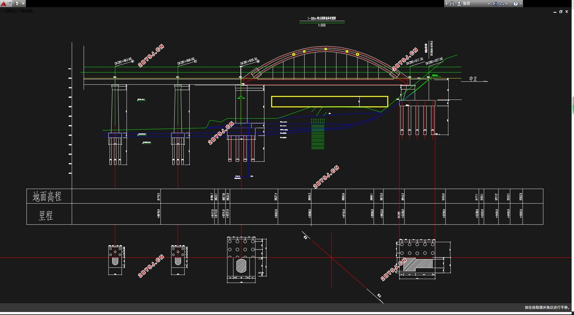
3.该桥拟建于桩号 DK281+929.30~DK282+009.30;
4.桥梁结构设计基准期:100 年;
5.抗震设防标准:按基本烈度 8 度设防,地震动峰值加速度 0.20g,地震动反应
谱特征周期分区为三区,场地土类型为Ⅱ类;
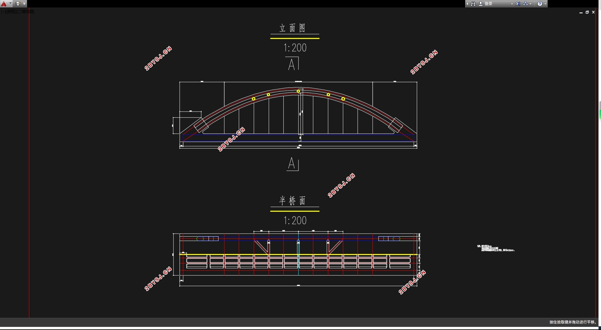
6.主桥上部结构拟采用系杆拱结构(钢管混凝土拱肋+预应力混凝土连续箱梁);桥
墩采用空心(或实心)墩身,矩形整体式承台,承台顶面位于地面(或河底)以下
10cm;基础采用钻孔灌注桩,桩基础按摩擦桩基础设计;
7.最小平曲线半径: 一般 3500m 困难条件下 2800m;要满足铁道线路要求;

目 录
摘 要 I
ABSTRACT II
第1章绪论 1
1.1.文献综述 1
1.1.1工程背景 1
1.1.1水文地质资料及设计依据 2
1.1.1主要技术标准和设计基础资料 2
1.2钢管混凝土系杆拱桥特点 5
1.3.系杆拱桥构造 6
第2章方案设计与比选 7
2.1方案主要设计尺寸 7
2.2 方案比选及采用 11
第3章设计荷载与荷载组合 13
3.1设计荷载 13
3.1.1恒荷载 13
3.1.2 活载 14
3.1.2 附加力 14
3.2 荷载组合 15
3.3迈达斯建模 15
3.3.1 建立节点 16
3. 3. 2建立单元 16
3.3.3单元划分 16
3.3.4边界条件 16
3.3.4迈达斯模型三视图 17
第4章内力计算(内力验算) 19
4.1 索力调整 19
4.2拱肋内力应力计算 19
4.2.1钢管截面面积As与钢管惯性矩Is 19
4.2.2 混凝土的截面面积Ac以及惯性矩Ic 19
4.2.3钢管混凝土的轴压刚度和抗弯刚度 19
4.3拱肋在各荷载作用下受力包络图 20
4.4拱肋3个截面在荷载下的内力验算 25
4.4.1拱顶截面内力验算 26
4.4.2 拱肋1/4拱截面内力验算 27
4.4.3拱脚截面内力验算 28
4.5混凝土拱肋应力验算 28
4.5.1主力组合作用 29
4.5.2 主力组合+风荷载作用 29
4.5.3主力组合+温度荷载作用 30
4.6横撑、K字撑内力及强度验算 30
4.7吊杆应力验算 31
4.8主梁内力计算及验算 32
第5章 结构配筋计算 35
5.1 主梁截面预应力配筋 35
5.2 主梁截面弯矩配筋 34
5.3 短横梁配筋 36
5.4纵梁配筋 37
第6章 结构验算 39
6.1 主梁截面承载力验算 39
6.1.1主梁轴力受拉正界面承载力验算 39
6.1.2 主梁跨中截面承载力验算 39
6.1.3 主梁斜截面承载力验算 40
6.2中纵梁承载能力极限状态验算 41
6.2.1中纵梁跨中正截面承载能力极限状态验算 41
6.2.2中纵梁斜截面承载能力极限状态验算 42
6.3横梁承载能力极限状态验算 44
6.3.1 横梁正截面承载力计算 44
6.3.2 横梁斜截面承载力计算 45
6.4边横梁承载力能力极限状态计算 46
6.4.1 边横梁正截面承载力计算 46
6.3.1 边横梁斜截面承载力计算 47
6.5正常使用极限状态计算 47
6.5.1 中纵梁正截面抗裂验算 47
6.5.2 中纵梁斜截面抗裂验算 48
6.5.3 横梁正截面抗裂验算 49
6.5.4 横梁斜截面抗裂验算 50
6.5.5 边横梁正截面抗裂验算 51
6.5.6 边横梁斜截面抗裂验算 52
结束语 54
致谢 56
参考文献 57
