二环线某钢结构人行天桥设计及结构验算(含CAD图)
无需注册登录,支付后按照提示操作即可获取该资料.
二环线某钢结构人行天桥设计及结构验算(含CAD图)(任务书,开题报告,论文计算书13000字,CAD图8张)
摘 要
随着我国经济的迅速发展,汽车数量在最近几年里迅速增长,结果导致城市中许多道路交汇处易发生拥堵。作为目前能够有效解决道路拥堵问题的人行天桥是城市道路系统中的重要组成部分,人行天桥不仅可以使人车分流、方便行人过街与建筑物联系,还能够有效地减少车流和人流的互相干扰,所以能够十分有效地改善路口的交通拥堵情况。
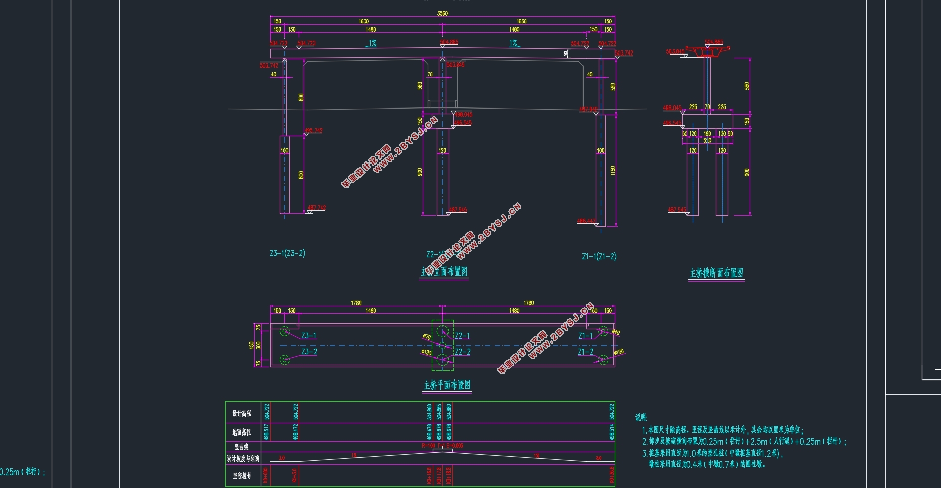
本次设计为二环线某钢结构人行天桥,拟采用17.8m+17.8m=35.6m的两跨结构,为简支等截面钢箱连续梁桥,梁高0.9m,梁宽4.5m,主梁采用工厂预制,现场直接吊装的施工方法。
本文主要对二环线某钢结构的人行天桥主梁、梯道梁、墩柱、桩基等各结构进行设计和计算,并利用Midas建立模型进行验算。
关键词:人行天桥;简支梁桥;钢箱梁
Abstract
With the rapid development of China's economy, the number of cars has increased sharply in recent years.Resulting in the traffic jam of many roads in the city. As a effective method to solve the problem in recent years, the pedestrian bridge is very important in urban road system.Pedestrian bridge not only can separate the peoplefrom the cars so that people can across the street conveniently and contact with buildings but also can effectively reduce the mutual interference of traffic flow and people.So it can be very effective to improve the intersection traffic congestion.
The design is a steel structure pedestrian bridge in the second ring.The bridge is proposed two span structure which is 17.8 m + 17.8 m = 35.6 m,.Cross section is simply supported steel box girder bridge in a row, The hight of beam is 0.9 m,the breadth of beam is 4.5 m.The girder use the method of factory prefabrication and hoist construction directly.
The structure of steel structure footbridge girder, ladder beam, pier column and pile foundation were designed and calculated in the thesis and Midas is used to establish a model for checking calculation.
Key Words:Pedestrian overpass; Simply supported bridge; Steel box girder


目录
第1章 绪论 1
1.1人行天桥的发展现状 1
1.2选题设计思想及意义 1
第2章 设计基础资料 2
2.1设计背景 2
2.2地质条件 2
第3章,桥型方案比选 4
3.1比选原则 4
3.2 设计方案 4
3.3方案比选 4
3.4方案选定 5
第4章 桥跨结构布置 8
4.1方案拟定 8
4.2技术指标与设计规范 8
4.3 技术指标 8
4.4主要材料 8
4.4.1 混凝土 8
4.4.2钢材 9
4.4.3其他材料 9
4.4.4焊接 9
4.5结构尺寸 9
4.5.1 本次人行天桥设计跨径的布置 9
4.5.2梁高的尺寸确定 9
4.5.3截面类型的选择和确定 9
4.5.4梁截面细部尺寸的选择 9
4.5.5梁截面 10
4.5.6 施工方法 11
第5章 Midas建模过程及内力计算 12
5.1建模过程 12
5.1.1定义截面 12
5.1.2定义材料 17
5.1.3建立结构三维模型 18
5.1.4定义时间依存材料 20
5.1.5添加静力荷载 21
5.1.6添加移动荷载 24
5.1.7定义边界条件 26
5.1.8定义组 26
5.19 定义施工阶段 29
5.2建模过程中遇到的问题 31
5.3分析过程 31
5.3.1 一期自重、二期恒载作用下的效应计算 31
5.3.2 移动荷载效应分析 39
第6章、主梁截面计算 49
6.1计算数据 49
6.2 荷载参数 49
6.3 其他计算主要参数 49
6.3.1材料设计参数 49
6.3.2 计算模型截面参数 49
6.4恒载状态平面计算内力及应力 50
6.5 运营阶段平面计算应力及检算 50
6.6 结构刚度检算 51
6.7整体稳定性验算 51
6.8局部稳定性验算 51
6.9支座反力及支座检算 51
6.10天桥上部结构竖向自震频率 52
第7章 梯道梁计算 53
7.1设计荷载及材料计算参数 53
7.1.1永久荷载 53
7.1.2 材料设计参数 53
7.2 荷载组合 53
7.3人行梯道模型及应力 53
7.3.1人行梯道模型 53
7.3.2 人行梯道应力 54
第8章 下部结构验算 57
8.1 概述 57
8.2 主墩截面验算 57
8.2.1承载能力极限状态验算 57
8.2.2 正常使用极限状态验算 58
8.2.3墩身抗压承载能力验算 58
8.3 桩基础验算 59
参考文献 61
致谢 63
