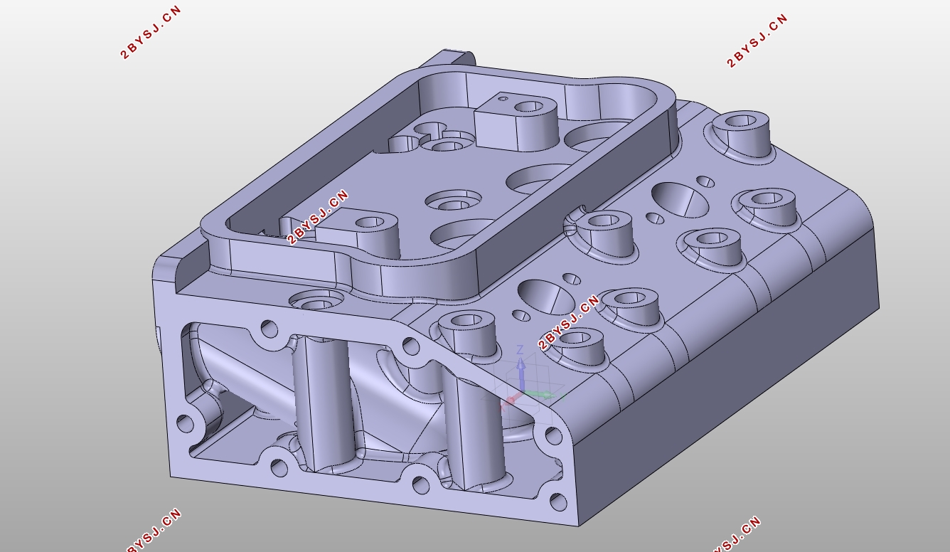
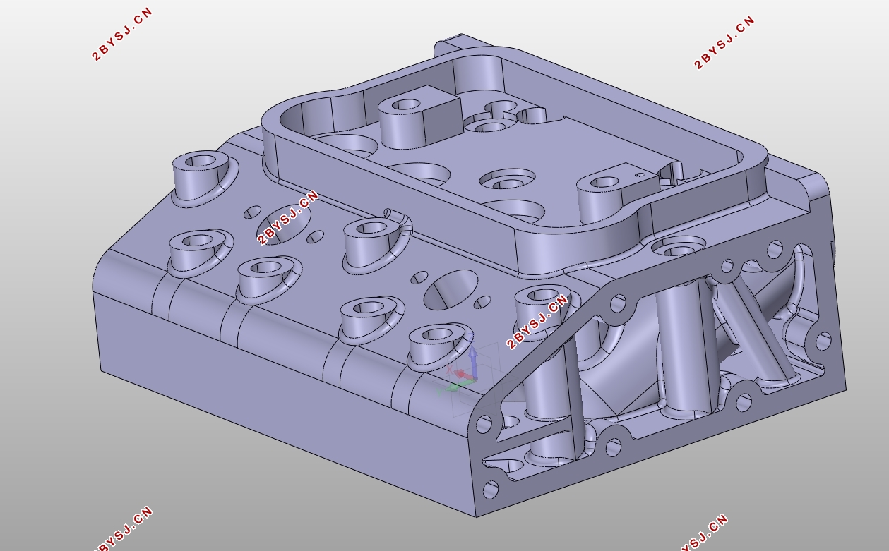
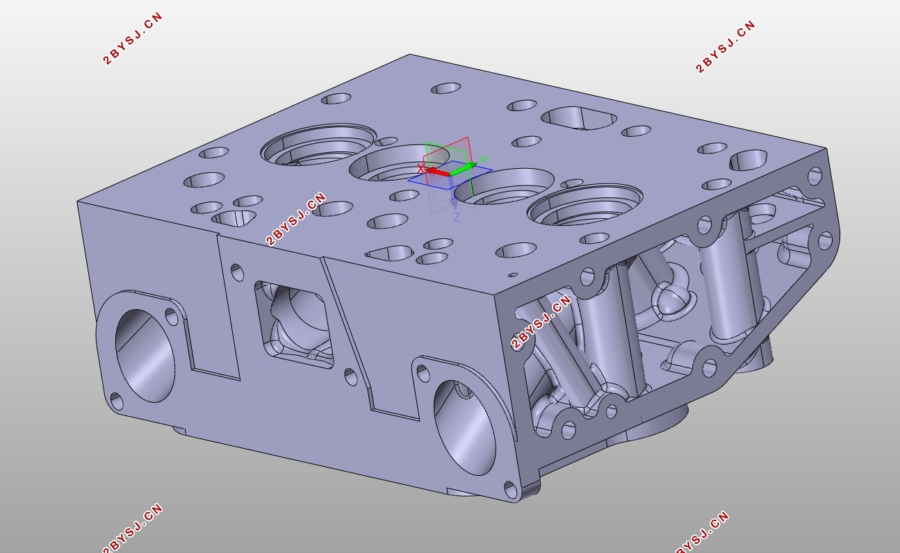
2100柴油机总体设计及气缸盖设计(含CAD图,CATIA三维图)
无需注册登录,支付后按照提示操作即可获取该资料.
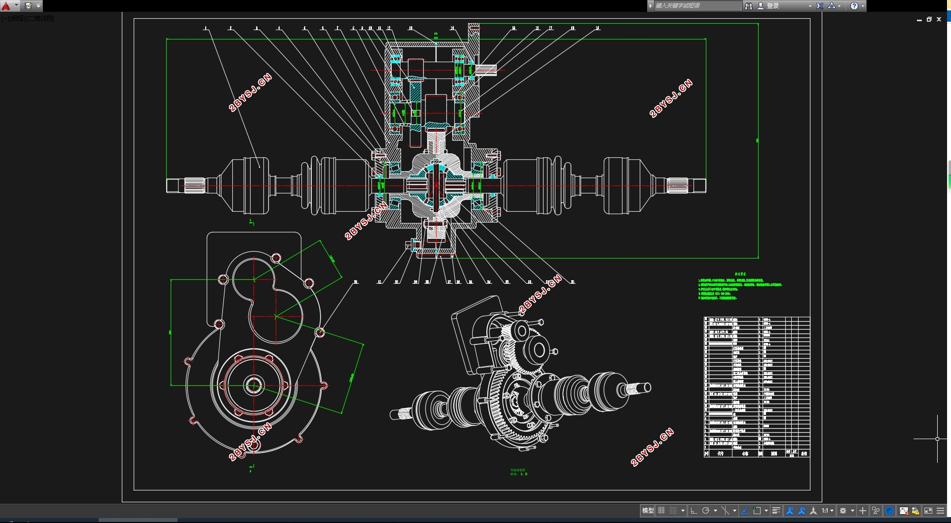
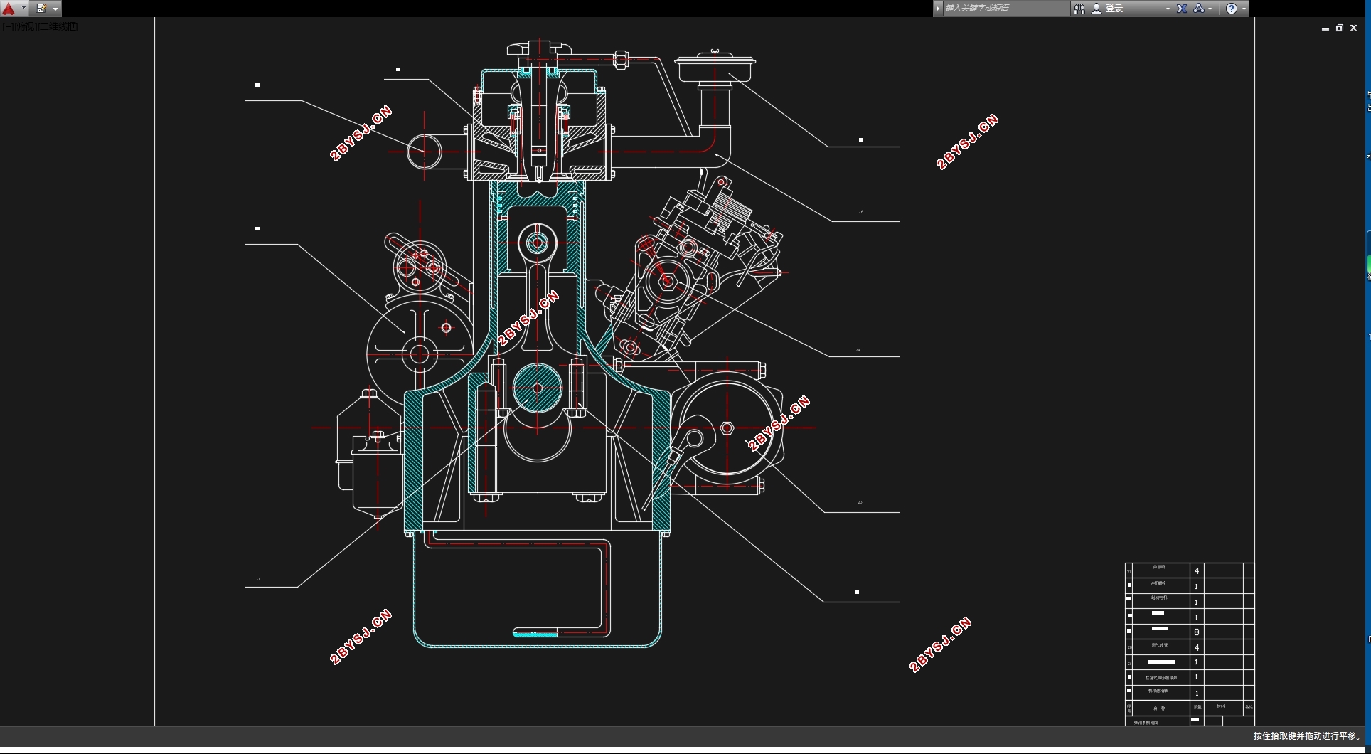
2100柴油机总体设计及气缸盖设计(含CAD图,CATIA三维图)(任务书,开题报告,文献摘要,外文翻译,论文说明书11500字,CAD图1张,CATIA三维图)
【摘要】
由于气缸盖工作条件十分恶劣,在设计过程中,气缸盖设计的优劣直接影响柴油机的性能和耐久性。气缸盖的主要设计内容有气缸盖形式的确定、气门数量、气缸盖螺栓布置、进排气道的尺寸计算和布置方式等。本文主要介绍根据柴油机性能指标选择主要的性能参数,重点阐述了柴油机气缸盖的设计过程,且对气缸盖结构的形式选择、进排气道设计、气缸盖螺栓的设计进行了讨论.并通过对气缸盖建模及有限元分析实现优化设计。
【关键字】:柴油机 气缸盖 设计 建模 有限元分析
Due to the severe working conditions of the cylinder head, the design of the cylinder head directly affects the performance and durability of the diesel engine during the design process. The design of the cylinder head includes the selection of the cylinder head shape, the determination of the number of valves, the selection and arrangement of the number of cylinder head bolts, the design and arrangement of the intake and exhaust passages, and the cooling measures of the valves and cylinders. . This article mainly introduces the selection of main performance parameters based on the diesel engine performance index, and focuses on the design basis and design process of the diesel engine cylinder head. At the same time, the selection of the cylinder head structure, the determination of the main dimensions, the design of the intake and exhaust passages, and the arrangement of the cylinder head bolts are discussed. The optimization design is achieved through cylinder head modelling and finite element analysis.
[Keywords]: Diesel Engine 、Cylinder Head、 Design 、Modeling Finite 、Element Analysis
2、柴油机的总体设计
2.1初始条件
发动机功率:Pe=37Kw; 转速n=3200 r/min; VL=2.164L ; ge≤265g/kw*h;
2.2发动机类型
2.2.1冲程数的选择
已知发动机的冲程数选择为四冲程,即τ=4
2.2.2冷却方式
为提高气缸冷却性能,采用水冷方式。
2.2.3气缸数与气缸布置方式
采用直列式二缸机。


目录
【摘要】 I
1.绪论 1
2、柴油机的总体设计 2
2.1初始条件 2
2.2发动机类型 2
2.2.1冲程数的选择 2
2.2.2冷却方式 2
2.2.3气缸数与气缸布置方式 2
2.3基本参数 2
2.3.1行程缸径比S∕D的选择 2
2.3.2气缸工作容积V和缸径D的选择 3
2.4 活塞组的结构设计 4
2.4.1 活塞的设计 4
2.4.2 活塞销设计 5
2.5 曲轴的结构设计 5
2.5.1 曲轴的工作条件和设计要求 5
2.5.2 曲轴的结构和材料 6
2.5.3 曲轴尺寸设计 6
2.6 连杆的设计 6
2.6.1 连杆的工作条件和设计要求 6
2.6.2 连杆材料的选择 7
2.6.3 连杆主要结构尺寸设计 7
3、气缸盖的设计 9
3.1气缸盖的工作条件 9
3.11气体作用力 9
3.1.2螺栓预紧力 9
3.1.3热应力 9
3.2气缸盖的设计要求 9
3.3气缸盖材料选择 10
3.4 气缸盖结构设计 10
3.4.1缸盖形式的选择 10
3.4.2气门数的确定 11
3.4.3缸盖螺栓数量的选择与布局 11
3.4.4进排气道的设计 12
3.4.5燃烧室及喷油器在气缸盖中的布置 13
3.4.6气缸盖冷却水道布置 14
3.4.7燃烧室的密封及汽缸垫设计 14
3.5 气缸盖基本尺寸确定 15
3.5.1气缸盖的高度 15
3.5.2底面壁厚 15
3.5.3其余尺寸 16
4、 曲柄连杆运动学计算 17
4.1 曲柄连杆机构运动计算 17
4.1.1 曲柄连杆比的选择 17
4.1.2 活塞运动规律 17
4 .2动力学计算 20
4.2.1 气体作用力的计算 20
4.2.2 惯性力的计算 20
4.3.2 总作用力的传递 22
5、气缸盖的热力学计算 23
5.1热力循环基本参数的确定 23
5.2热力过程具体计算 24
5.2.1 绝热压缩过程 24
5.2.2 定容增压过程 24
5.2.3 定压膨胀过程 24
5.2.4 绝热膨胀过程 25
5.2.5 p-V图向p-α图的转换 25
6、基于CATIA的实体建模 26
6.1 CATIA产品概述 26
6.2气缸盖建模 27
6.2.1打开软件 27
6.2.2.草图绘制 27
6.2.3.完成后的模型 29
6.3本章小结 30
7.基于ANSYS的有限元分析 30
7.1ANSYS软件介绍 30
7.2 导入模型 31
7.3结果分析 33
7.4本章小结 33
8 全文总结与展望 34
9、致谢 34
10、参考文献 35
