汽车减震器设计(含Pro/E三维图)
无需注册登录,支付后按照提示操作即可获取该资料.
汽车减震器设计(含Pro/E三维图)(任务书,开题报告,论文说明书11000字,Pro/E三维图)
摘要
减震器是安装在车体与负重轮之间的一个阻尼元件,其作用是衰减车体的振动并阻止共振情况下车体振幅的无限增大,能减小车体振动的振幅和振动次数,因而可以延长弹性元件的疲劳寿命和提高人乘车的舒适性。
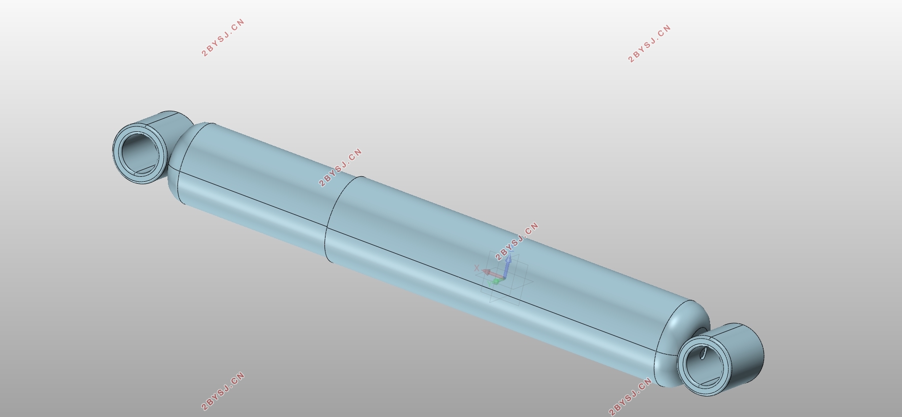
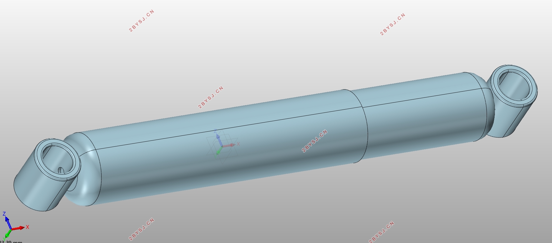
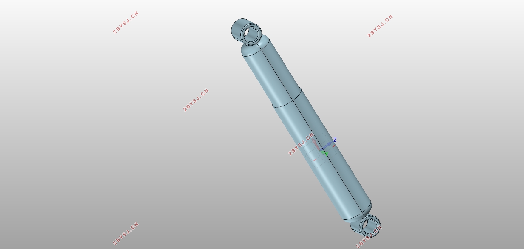
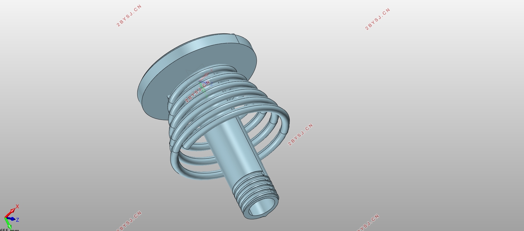
本次设计的是双作用筒式减震器。先对相对阻尼进行确定,之后对缸筒、活塞杆、导向座和活塞的宽度以及各阀系进行设计计算,并对活塞杆的强度和稳定性进行校核,最后用Pro/E对减震器的主要零件进行三维建模。
关键词:减震器 相对阻尼 三维建模
ABSTRACT
Shock absorber is installed in a damping between the body and the bogie wheel component, its effect is attenuation vibration of car body and preventing resonance case body amplitude increases indefinitely, can reduce the body vibration amplitude and vibration frequency, and thus can prolong the fatigue life of elastic element and improve ride comfort.
This design is a double-acting cylinder shock absorbers. After first to determine the relative damping of cylinder, piston rod, guide, and the width of the piston and the valve system to carry on the design calculation, and to check the strength and stability of the piston rod, finally using Pro/E 3D modeling was carried out on the shock absorber of the major parts.
Keywords: shock absorber relative damping 3D modeling

目录
摘要 I
ABSTRACT II
目录 III
第一章 绪论 1
1.1课题的背景及意义 1
1.2减振器国内外是发展状况 1
1.3设计的主要研究内容 3
第二章 汽车减震器结构设计 4
2.1液压减震器的分类 4
2.2双作用筒式减震器的结构 4
2.3双向作用筒式减震器工作原理 6
第三章 减震器各部件的设计计算及校核 7
3.1相对阻尼系数和阻尼系数的确定 7
3.1.1悬架弹性特性的选择 7
3.1.2相对阻尼系数 的选择 7
3.1.3减振器阻 尼系数的确定 8
3.2最大卸荷力 的确定 9
3.3缸筒的设计计算 9
3.4活塞杆的设计计算 10
3.5导向座宽度和活塞宽度的设计计算 10
3.6固定连接的结构形式 10
3.7 减震器油封设计 11
3.8 锥形弹簧 12
3.9减振器油的选择 12
3.10减震器阀系设计 13
3.10.1伸张行程流体力学模型的建立 13
3.10.2压缩行程流体力学模型的建立 15
3.11各阀系模型的建立 17
3.11.1伸张阀模型的建立 17
3.11.2流通阀模型的建立 18
3.11.3压缩阀模型的建立 19
3.11.4补偿阀的力学模型 20
3.12强度校核 21
3.13稳定性的校核 22
第四章 减震器的三维建模 23
4.1螺纹杆及弹簧 23
4.1.1螺纹杆 23
4.1.2弹簧 24
4.2前后套筒 25
4.2.1前套筒 25
4.2.2后套筒 25
4.3各个阀系 26
4.4活塞杆 29
4.5装配成图 29
第五章 全文总结及展望 31
参考文献 32
致谢 34
