1240型载货汽车后轮制动器设计(含CAD零件图装配图,CATIA三维图)
无需注册登录,支付后按照提示操作即可获取该资料.
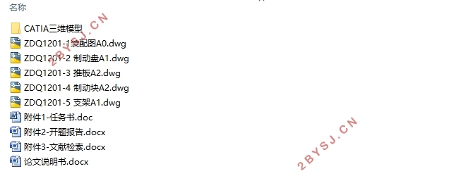
1240型载货汽车后轮制动器设计(含CAD零件图装配图,CATIA三维图)(任务书,开题报告,文献摘要,论文说明书12000字,CAD图5张,CATIA三维图)
摘 要
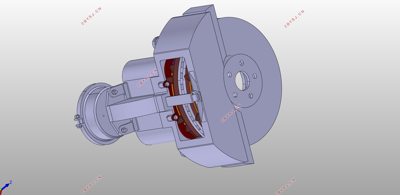
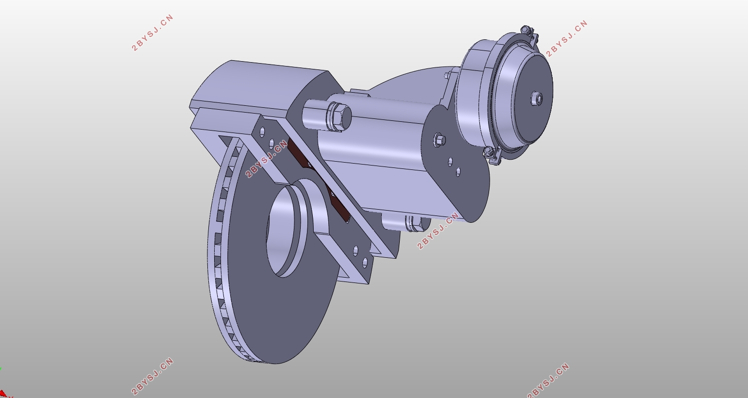
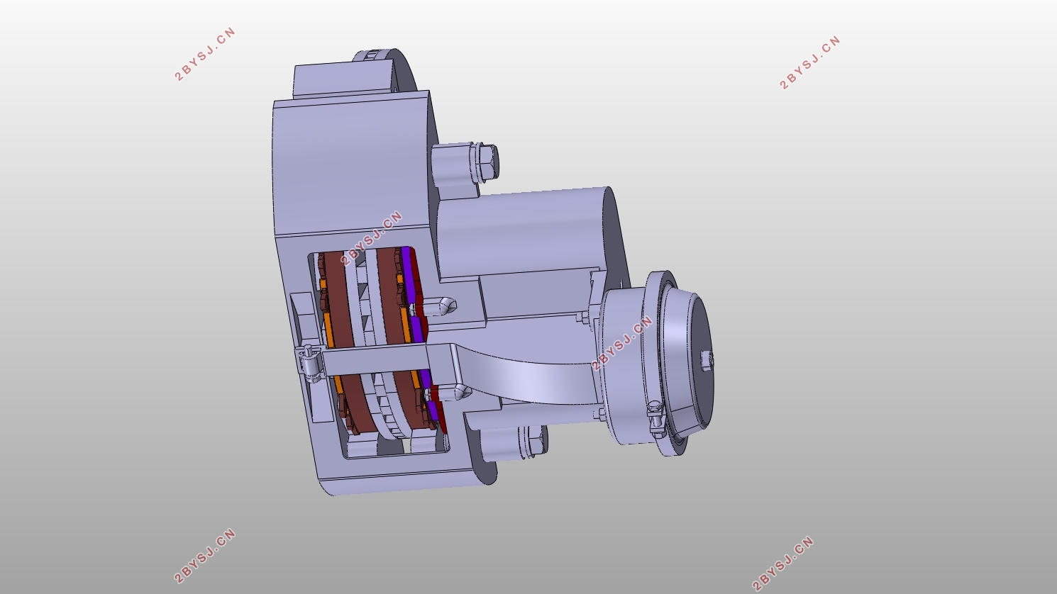
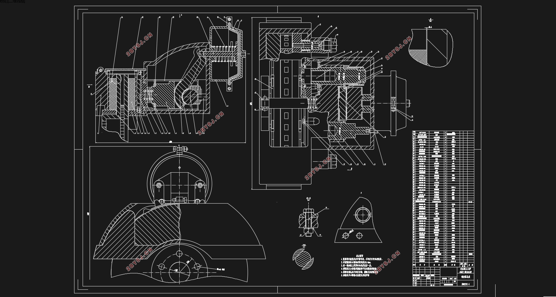
本文主要对1240型载货汽车进行后轮制动器的设计,而后轮制动器主要有鼓式制动器和盘式制动器两种。通过对两种制动器的优缺点的对比分析,再根据中国的道路情况和驾驶员的行驶习惯,选择了盘式制动器。而由于1240型载货汽车属于重型载货汽车,液压驱动机构无法提供足够的制动力矩,故采用当前国内外比较流行、先进的气压盘式制动器。
1240型载货汽车为三轴货车,中后轴为并联双轴式,故制动时各轴的车轮额垂直载荷的计算和传统二轴汽车有所区别。考虑到该车采用的是平衡悬架,本文首先将该车进行模型简化,粗略算出前轴垂直载荷和制动力,在根据并联双轴汽车各轴垂直载荷的方法算出中后轴垂直载荷。另外在进行制动间隙调整机构设计时,为了能够保证制动推力能够平稳输出,对目前市面上的间隙调整机构进行一些改动,采用双推杆结构型式,达到更好地制动效果。
关键词:气压盘式制动器;平衡悬架;间隙自动调整机构
Abstract
This paper mainly carries on the design of the rear wheel brake of the type of 1240 truck. There are two kinds of brake which are drum brake and disc brake.Through the comparison of the advantages and disadvantages of the two kinds of brake and according to the situation of China's road and the driving habits of the driver,disc brake is selected.Because the type of 1240 truck is a heavy duty truck,the hydraulic drive mechanism can not provide sufficient braking torque,so I choose the air disc brake which is advanced and popular at home and abroad.
The type of 1240 truck has three axles,the middle axle and rear axle are Parallel biaxial.So the calculation of the vertical load on each axle is different from that of the traditional two axles vehicle when the truck is braking.Taking into account that the truck use balanced suspension,in this paper, the model is simplified.So I can roughly calculate the vertical load and braking force of front axle.Then calculate the vertical load of each axle in accordance with the method of parallel biaxial’s calculation.In addition to the design of the brake clearance adjustment mechanism,In order to ensure that the braking force can be output smoothly,I make some changes on agency which is used in current market.Double push rod structure used to achieve better braking effect.
Keyword:air disc brake; Balance suspension; Gap automatic adjusting mechanism
3.11240型货车具体参数
3.1.1 尺寸参数
长:9630mm;宽:2470mm;高:2980mm
质心到前轴的距离:2874mm(空载);4016mm(满载)
质心到后轴的距离:2126mm(空载);984mm(满载)
轴距:4350+1300/2=5000mm(计算时将中后桥进行简化,故中后轴等效轴取两轴中间点)
前轴轮距:1940mm;中后轴轮距:1860mm
质心高度:800mm(空载);1500mm(满载)
3.1.2 质量参数
整备质量:8040kg
满载质量:24250kg
前轴载荷:3420kg(空载);5000kg(满载)
后轴载荷:4620kg(空载);19250kg(满载)
3.1.3 性能参数及其他参数
最高行驶速度:90km/h
车速为80km/h(22.2m/s)时,制动距离为53m
轮胎型号:10.00R20
轮胎静力半径:493mm
3.21240型货车的模型简化
本设计中1240型货车为三轴式货车,故在进行制动分析时,不能直接采用二轴式制动模型进行受力分析。但是由于该车后轮采用的是平衡悬架,由《汽车构造》(陈家瑞编著,人民交通出版社) 可知,平衡悬架所连接的中后桥车轮的垂直载荷将会平均分配,从而保证两车桥上的垂直载荷在任何情况下都相[9]。这样,我们就可以将中后桥进行简化,将中后桥车轮载荷等效到平衡悬架心轴位置,从而将三轴问题简化成两轴汽车的制动模型。


目录
摘 要 I
Abstract II
第1章 绪论 1
第2章 制动器的结构型式和制动驱动机构的选择 3
2.1 制动器结构型式的选择 3
2.2 制动器驱动机构的选择 4
第3章 制动器主要参数和计算 5
3.11240型货车具体参数 5
3.1.1 尺寸参数 5
3.1.2 质量参数 5
3.1.3 性能参数及其他参数 5
3.21240型货车的模型简化 5
3.3 简化模型前后轴车轮垂直载荷的计算 6
3.4 简化模型地面制动力的计算 7
3.51240型货车各轴垂直载荷的计算 8
3.6 各轴车轮制动器制动力矩的计算 10
3.7 制动力分配系数的计算 10
第4章 制动器主要零件设计 12
4.1 制动盘 12
4.2 制动钳 13
4.3 制动块 13
4.3.1 摩擦衬块的内半径 和外半径 14
4.3.2 摩擦衬块的工作面积A 14
4.4 摩擦衬块磨损特性的校核计算 14
4.5制动器作用半径的计算 15
4.6 制动器工作间隙的自动调整 16
4.6.1 气压盘式制动器制动原理分析 16
4.6.2 间隙自动调整机构工作原理分析 17
4.6.3 压力臂的设计计算 19
4.6.4 调整环的设计计算 19
第5章 制动驱动机构的计算设计 21
5.1 制动驱动机构的结构型式 21
5.2 制动管路的多回路系统 21
5.3 气压制动驱动机构制动气室的设计计算 22
5.3.1 制动气室 22
5.3.2 制动气室推杆行程 22
第6章 结论 23
参考文献 24
附录A 25
摩擦衬块磨损特性的校核计算 25
附录B 27
1240型载货汽车后轮制动器三维模型 27
致谢 28
