有孔筋弯板零件成型工艺与冲压模具设计(含CAD零件图装配图,UG三维图)
无需注册登录,支付后按照提示操作即可获取该资料.
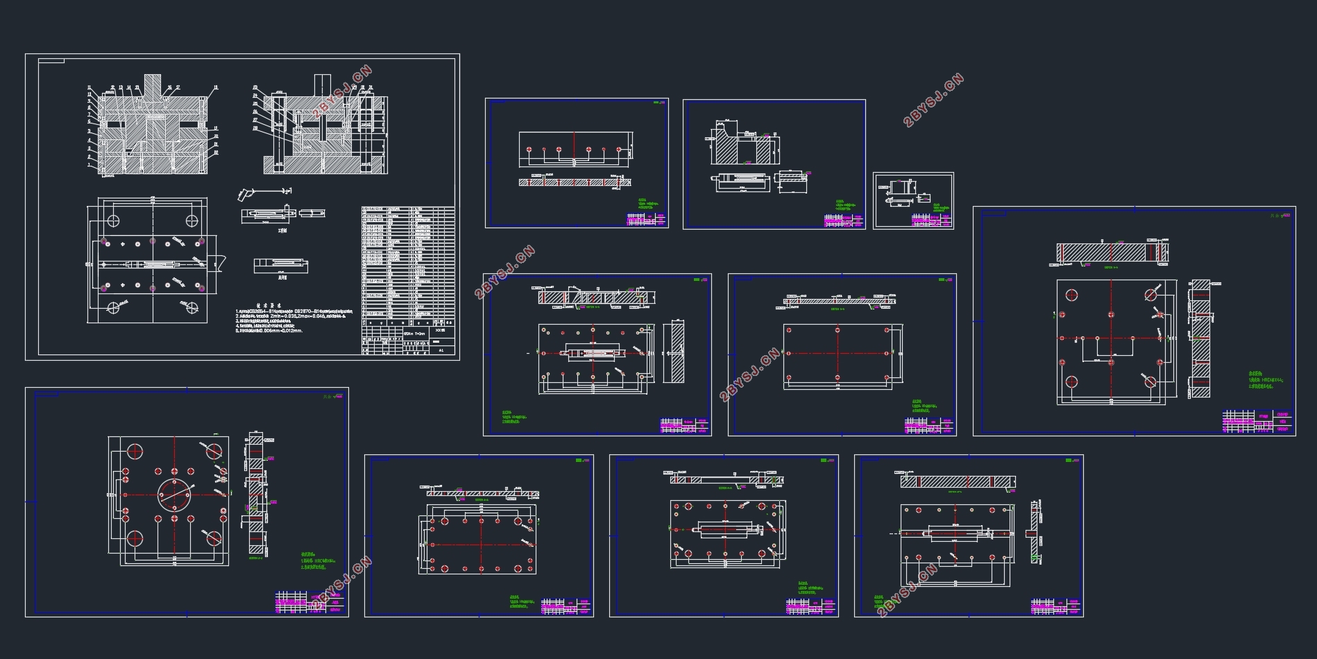
有孔筋弯板零件成型工艺与冲压模具设计(含CAD零件图装配图,UG三维图)(论文说明书13000字,CAD图12张,UG三维装配图)
摘 要:模具作为国家工业发展的基石,在所有的生产及加工设备中,其中的零配件基本有60%~90%都是由模具生产出来的。所以模具的设计与加工水平决定着所有产品的效益与质量。
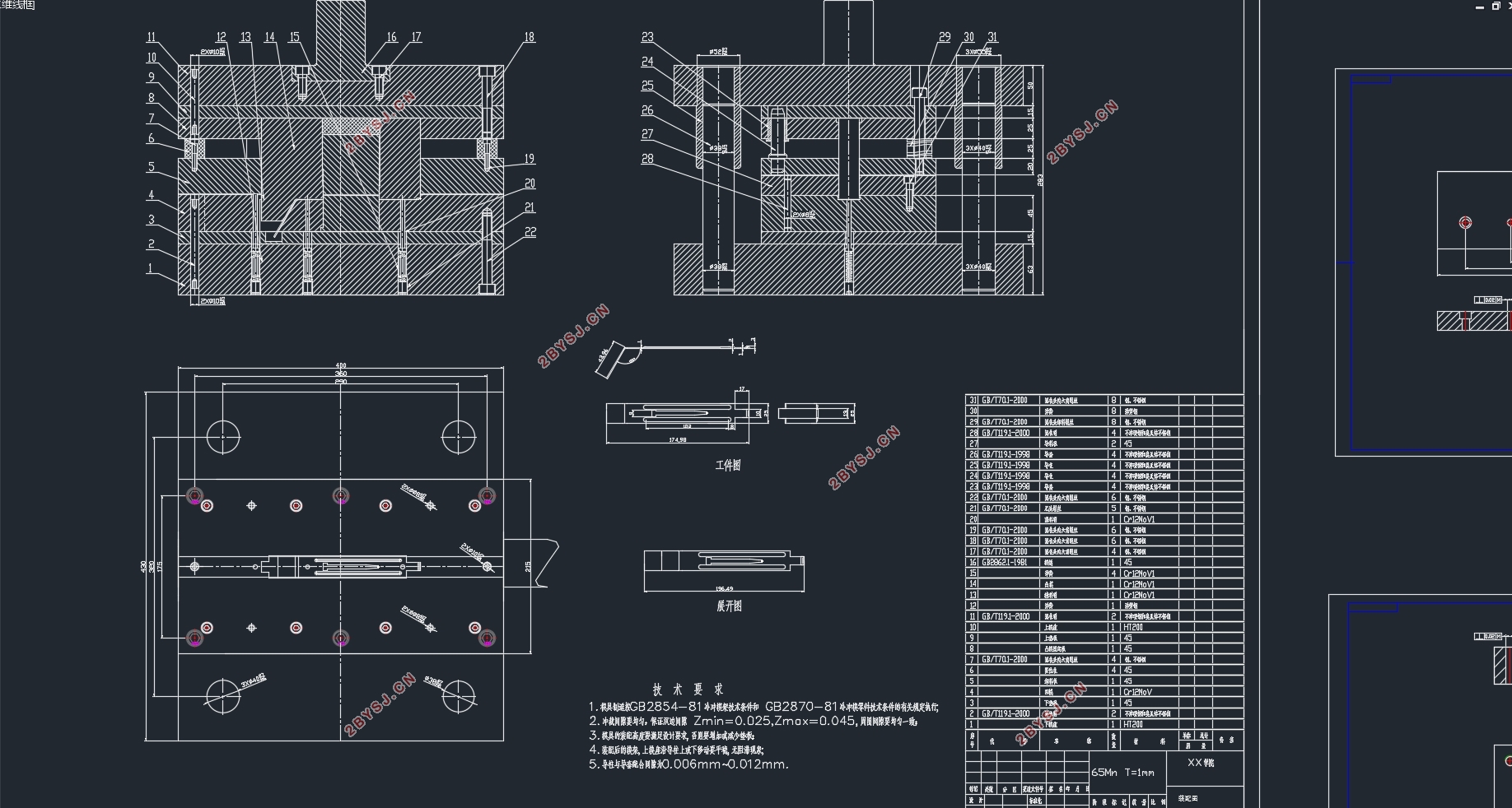
本次主要是对一种有孔筋弯板进行冲压模具设计,在本次有孔筋弯板零件的加工过程中需要弯曲,落料,工序,所以本次设计采用复合模具的方案对零件进行设计,使用计算机软件与模具的设计相结合,使模具上的错误修改可以更加的便捷,同时也可以通过软件对所设计的模具进行检验,可以在模具的加工前大大的降低模具设计的失误,能有效的降低设计失误所带来的成本的增加。
关键词:冲压模设计;支架;设计;弯曲
Forming technology and die design of bending plate parts with hole rib
Abstract:Die As the cornerstone of National Industrial Development, in all production and processing equipment, of which the basic parts of 60% ~ 90% are produced by the mold. So die design and processing level determines the efficiency and quality of all products. This time is mainly a kind of spring hook stamping die design, in this spring hook parts processing process needs punching, bending, blanking, undulating, embossing and other processes, so this design used progressive die design of the parts, the use of computer software combined with Die Design makes it easier to correct errors in the die, and also makes it possible to check the designed die by software, can greatly reduce the mold design error before the processing, can effectively reduce the design error caused by the increase in costs.
Key words:Stamping Die Design; Spring Hook; Progressive Die; Bending
有孔筋弯板零件分析
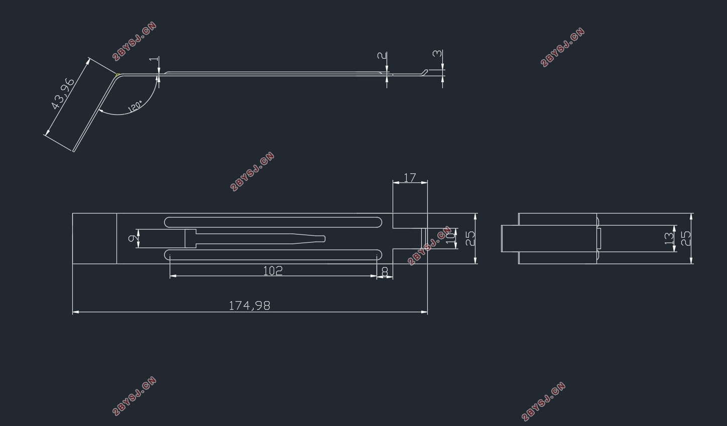
在对模具的设计之前首先需要对零件的CAD电子图档的二维零件图进行绘制,本次设计的有孔筋弯板零件的零件图绘制后如图2.1所示,由零件图可以知道本次设计的零件是一个非常复杂的冲裁零件,所设计的有孔筋弯板零件的材料厚度为1mm,根据零件的形状以及作用可以选择零件的加工材料为65Mn钢,本次设计的有孔筋弯板零件具有落料、弯曲等不同的工序,而且该零件的弯曲形状较为复杂,设计时应特别注意零件的弯曲工序。
有孔筋弯板零件的生产批量为:大批量生产
有孔筋弯板零件的材料为:65Mn钢
有孔筋弯板零件的料厚为:1mm


目 录
有孔筋弯板零件成型工艺与模具设计 I
Forming technology and die design of bending plate parts with hole rib I
目 录 1
1.1 冲压工艺与模具的发展方向 3
1.1.1 成形工艺与理论的研究 3
1.1.2 模具工业的发展趋势 3
1.2 模具工业在国民经济中的作用 5
2 有孔筋弯板零件工艺分析 7
2.1 有孔筋弯板零件分析 7
2.2冲压件材料特性 8
2.3 材料成型性能 8
2.4确定冲裁工艺方案 8
3 有孔筋弯板冲压模具设计 10
3.1 毛坯尺寸参数的计算 10
3.2 排样设计 11
4 有孔筋弯板复合模的工艺计算 13
4.1 压力的计算 13
4.1.1冲裁力的计算 13
4.1.2弯曲力的计算 14
4.1.3 模具的总冲压力 15
4.2 压力中心计算 15
4.3 冲压设备的选取 15
4.4 冲裁间隙 16
4.4.1 冲裁间隙分类 17
4.4.2 间隙值和确定间隙方法 17
4.5 计算刃口 17
4.5.1 刃口尺寸计算准则 17
4.5.2 刃口尺寸计算 18
4.5.3计算凸、凹模刃口的尺寸 18
4.5.4 弯曲模具尺寸的计算 19
4.5.5弯曲回弹 19
5 模具及零件设计与选用 21
5.1模具主要零件 21
5.2 模架和模座的选择 23
5.3垫板的选用 24
5.4卸料机构的设计 25
5.5定位零件的设计 26
5.6弹性元件的选用 26
5.7卸料板 26
6 压力机的校核 28
6.1 压力机的压力的校核 28
6.2 压力机的滑块的行程校核 28
6.3 压力机的行程次数 28
6.4 滑块模柄孔尺寸 28
6.5 模具的闭合高度 28
7 模具的总体结构设计 29
8总 结 30
参考文献 31
致 谢 32
