钢筋自动折弯机(钢筋弯曲机)的结构设计
无需注册登录,支付后按照提示操作即可获取该资料.
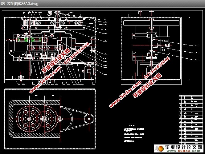
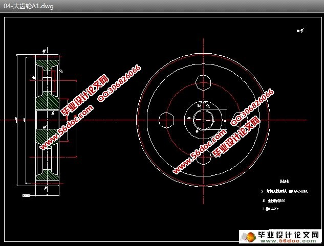
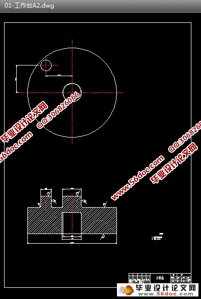
钢筋自动折弯机(钢筋弯曲机)的结构设计(开题报告,中期报告,外文翻译,论文说明书15000字,CAD图9张)
摘要
钢筋弯曲机是建筑工地必不可少的机械,能有效的提高生产效率,减少工人劳动强度,提高钢筋弯曲精度。
本文所设计的钢筋弯曲机适用于弯曲Φ4-Φ20毫米的钢筋,其传动机构为全封闭式,采用两级变速,工作转速满足弯曲要求,使加工效率高、加工精度高、劳动强度小。钢筋的弯曲角度由工作盘侧面的触杆与限位开关调节,打弯钢筋后可以自动归位,能实现弯曲角度的自动化。
本文对V带轮和圆柱传动齿轮进行了设计计算,并对轴、键和轴承等关键部件进行了力学分析计算和强度校核,表明该钢筋弯曲机完全符合设计要求。与目前实际应用的各种钢筋弯曲机相比,本机操作简单,弯曲形状一致,调节方便,性能稳定。
关键词:钢筋弯曲机;弯曲角度;弯矩;主轴扭矩
Structure design of reinforced automatic bending machine
Abstract
Bending machine for steel bars is essential to building industry, which can effectively improve the production efficiency, reduce labor intensity and improve the accuracy of bending for the steel bars.
The bending machine designed is suitable for the steel bars with various diameters from 4 to 20 millimeters, which is enclosed entirely. With two speed transmission, the bending machine has the characteristic of high efficiency, high precision and low labor intensity. The bending angle is adjusted by the bar along the working disc and the limit switch, with which the bar having been bent can return to the original position to realize the automation of bending process.
Compared to the bending machines applied presently, the machine designed has some obvious advantages, such as easy operating, uniformity of bending angle, convenient adjustment and high stability. The design and calculation for the V pulley and cylindrical gear is completed, in addition, some key parts of the machine are verified, which suggests that the bending machine designed satisfy the demand of the plan.
Key words: bending machine for rebar; bending angle; bending moment; twisting moment of spindle


目 录
1 绪论 1
1.1综述 1
1.2折弯机的发展和研究情况 2
1.2.1折弯机的国内外发展状况 2
1.2.2折弯机发展趋势 6
1.3课题背景 7
1.4新型钢筋折弯机的特点及组成部分 7
1.5本文主要研究工作 8
2 弯矩计算及电动机选择 12
2.1折弯方案 12
2.1.1钢筋受力情况 12
2.1.2钢筋弯曲机所需主轴扭矩及功率 12
2.2材料达到屈服极限的始弯矩 13
2.2.1按Ф20螺纹钢筋公称直径计算 13
2.2.2钢筋变形硬化后的终弯矩 13
2.2.3钢筋弯曲所需距 13
2.2.4电动机功率 13
3 确定传动比及运动参数 14
3.1 分配传动比 14
3.2 计算传动装置的运动和动力参数 14
4 V带传动设计 16
4.1 V带轮的设计计算 16
5 圆柱齿轮设计 19
5.1选择材料 19
5.2按接触强度进行初步设计 19
5.3齿轮校核 20
5.3.1 校核齿面接触强度 20
5.3.2 校核齿根的强度 22
6 第三级圆柱齿轮的设计 24
6.1选择材料 24
6.2按接触强度进行初步设计 22
6.3校核齿轮 24
7 轴的设计 29
7.1计算作用在轴上的力 29
7.2计算支力和弯矩 29
7.3对截面进行校核 31
8 主轴的设计 34
8.1计算作用在轴上的力 34
8.2计算支力和弯矩 32
8.3对截面进行校核 36
9 轴承和键的校核 38
9.1轴承校核 38
9.2 键的校核 39
10 结论 40
参考文献 41
致谢 42
