加工中心夹具快速拆装装置设计(含CAD零件图装配图)
无需注册登录,支付后按照提示操作即可获取该资料.
加工中心夹具快速拆装装置设计(含CAD零件图装配图)(任务书,开题报告,论文说明书10000字,CAD图6张)
摘要
因为加工中心具有工序集中,对加工对象的适应性强,加工精度高,加工生产率高,操作者的劳动强度减轻,经济效益高,有利于生产管理的先现代化。所以,现在加工中心逐渐成为机械加工业中最主要的设备,它加工范围广,使用量大。近年来随着加工中心逐渐成为机械加工业中最主要的设备,其应用越来越广。但是由于加工中心多采用封闭或者半封闭模式,所以加工中心的夹具在拆装时极其不方便,而且加工中心的夹具重量一般在500kg以上,而对于车间中广泛采用的吊钩、吊环等起重设备并不能很好的使用。而目前车间中负责加工中心夹具拆装的设备一般是叉车来负责的,但是叉车因为本身的用途、操作及结构特点,在实际操作过程中并不能准确快速的实现夹具的拆装。因此为了保证加工中心夹具的快速拆装,提高加工中心的工作效率,参考叉车的工作机制,设计制造出能够方便操作,并且精度高效率快的加工中心夹具快速拆装装置——夹具换型小车。而其实际就是对起重技术的运用。
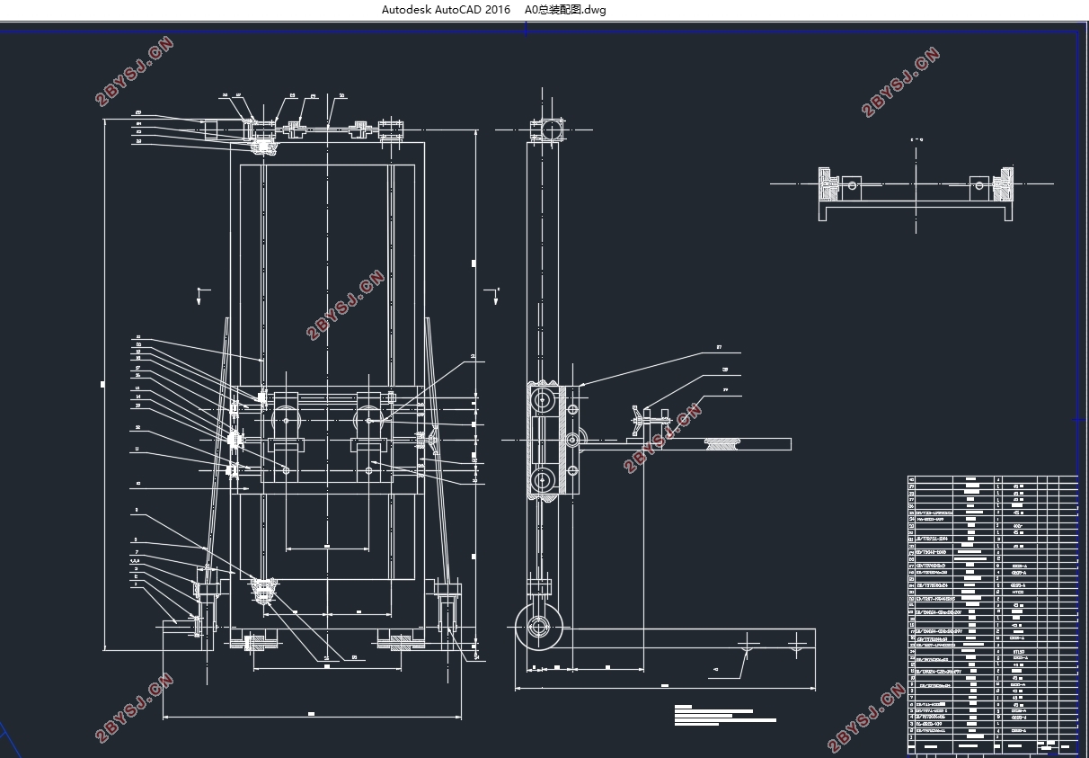
夹具换型小车要实现的功能有:起重垂直升降,水平前后及水平左右调整机构,设备可移动性。具体要求是:最大起重量达到1吨,尺寸符合车间空间要求,通过性好。
关键词:夹具换型小车,升降机构,水平调整机构
Abstract
Because the machining center with the process of concentration of object processing adaptability, high machining precision, high productivity machining, reduce the labor intensity of the operator, high economic benefit, is conducive to the production management to the modernization. Therefore, now the processing center has gradually become the most important equipment in the mechanical processing industry, it has a wide range of processing, the use of large.In recent years, with the machining center has gradually become the mostimportant equipment in the mechanical processing industry, its application is moreand more widely.But due to the machining center using a closed or semi closed mode,so machining center fixture in the disassembly extremely inconvenient .Besides machining center fixture weight general is more than 500kg, and the widely used in workshop of hook, rings up heavy equipment are not very good use for it.And the workshop responsible for assembling and disassembling fixture of machining center equipment is generally forklift responsible, but because of his application,operation and structure characteristics, in actual operation process and can not accurately and quickly realize the fixture of disassembly.Therefore in order to ensure the quick assembly and disassembly of the machining center fixture, improve the efficiency of the machining center.I reference forklift working mechanism, design and manufacture of a convenient operation and quick precision and high efficiency machining center fixture rapid dismounting device, the car for fixture. And its practice is the application of the lifting technology.
The functions for the car includes lifting vertical and horizontal, and the level of the level before and after the adjustment mechanism, the device can be mobile.The specific requirements are: the maximum weight of 1 tons, the size of the workshop space requirements, through the good.
Key words: the car for fixture,lifting mechanism,horizontal adjusting mechanism
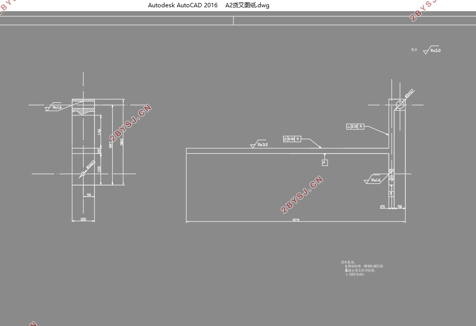
通过查阅资料可知,货叉尺寸主要取决于起重量Q、载荷中心距c,已知起重量Q=1吨,载荷中心距c=450mm,暂定货叉的基本参数及尺寸为:
货叉长度 l=900mm
货叉垂直高度 h=382mm
货叉断面尺寸 a b=25 100mm²
货叉两铰点中心距 d=350mm
货叉外伸距 e=0
同时,在货叉的上面焊接有右边的固定支座及左边的移动支座,两者通过转动手轮实现货叉对夹具的水平前后的微调。如图3-1所示。
固定支座尺寸:
高度 =146mm
=26mm
长度 =100mm
断面尺寸1 =50 150mm²
断面尺寸2 =25 100mm²
移动支座尺寸:
高度 =146mm
=26mm
长度 =550mm
断面尺寸3 =50 150mm²
断面尺寸4 =25 100mm²


目录
第1章绪论•••••••••••••••••••••••••••••••••••••••••••••••••••••••••••••••••••1
1.1加工中心夹具快速拆装装置设计选题的目的及意义•••••••••••••••••••1
1.2夹具换型小车的发展现状及前景展望••••••••••••••••••••••••••••••1
1.3课题主要内容及要求••••••••••••••••••••••••••••••••••••••••••••2
1.4研究采用的技术方案及措施••••••••••••••••••••••••••••••••••••••2
第2章夹具换型小车结构总述••••••••••••••••••••••••••••••••••••••••••4
2.1门架简介及设计要求••••••••••••••••••••••••••••••••••••••••••••4
2.2门架系统的运动与安装关系••••••••••••••••••••••••••••••••••••••4
第3章货叉的设计计算••••••••••••••••••••••••••••••••••••••••••••••••6
3.1货叉基本参数和尺寸的确定••••••••••••••••••••••••••••••••••••••6
3.2货叉的计算简图••••••••••••••••••••••••••••••••••••••••••••••••7
3.3货叉的强度验算••••••••••••••••••••••••••••••••••••••••••••••••7
3.3.1计算载荷P的确定••••••••••••••••••••••••••••••••••••••••••8
3.3.2安全系数n的确定••••••••••••••••••••••••••••••••••••••••••9
3.3.3计算最大正应力••••••••••••••••••••••••••••••••••••••••••••9
3.3.4强度验算••••••••••••••••••••••••••••••••••••••••••••••••••9
3.4货叉的刚度验算••••••••••••••••••••••••••••••••••••••••••••••••9
3.5货叉挂钩形式的确定•••••••••••••••••••••••••••••••••••••••••••10
第4章叉架及叉板的设计计算•••••••••••••••••••••••••••••••••••••••••11
第5章门架的设计计算•••••••••••••••••••••••••••••••••••••••••••••••13
5.1门架的构造•••••••••••••••••••••••••••••••••••••••••••••••••••13
5.2门架强度的计算•••••••••••••••••••••••••••••••••••••••••••••••13
5.3滑动丝杠受力分析•••••••••••••••••••••••••••••••••••••••••••••14
5.4门架设计计算•••••••••••••••••••••••••••••••••••••••••••••••••16
5.4.1门架的弯矩校核••••••••••••••••••••••••••••••••••••••••••17
5.4.2门架的刚度计算••••••••••••••••••••••••••••••••••••••••••18
第6章其他机构•••••••••••••••••••••••••••••••••••••••••••••••••••••21
6.1电动机的选择•••••••••••••••••••••••••••••••••••••••••••••••••21
6.2轴承的选择•••••••••••••••••••••••••••••••••••••••••••••••••••22
总结••••••••••••••••••••••••••••••••••••••••••••••••••••••••••••••••••23
参考资料••••••••••••••••••••••••••••••••••••••••••••••••••••••••••••25
致谢••••••••••••••••••••••••••••••••••••••••••••••••••••••••••••••••26
