
激光雕刻机设计(含CAD零件装配图爆炸图)
无需注册登录,支付后按照提示操作即可获取该资料.
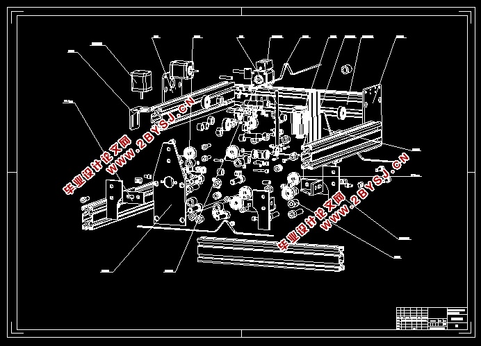
激光雕刻机设计(含CAD零件装配图爆炸图)(任务书,论文说明书23000字,CAD图纸7张,实习调研报告)
摘 要
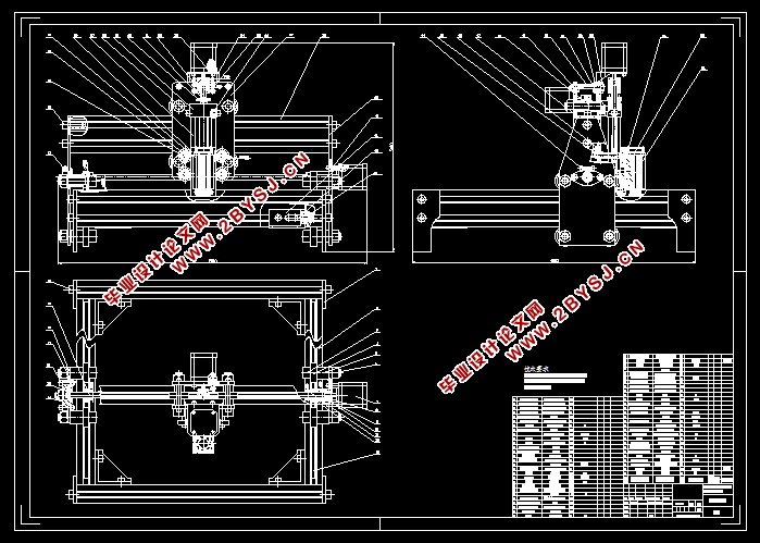
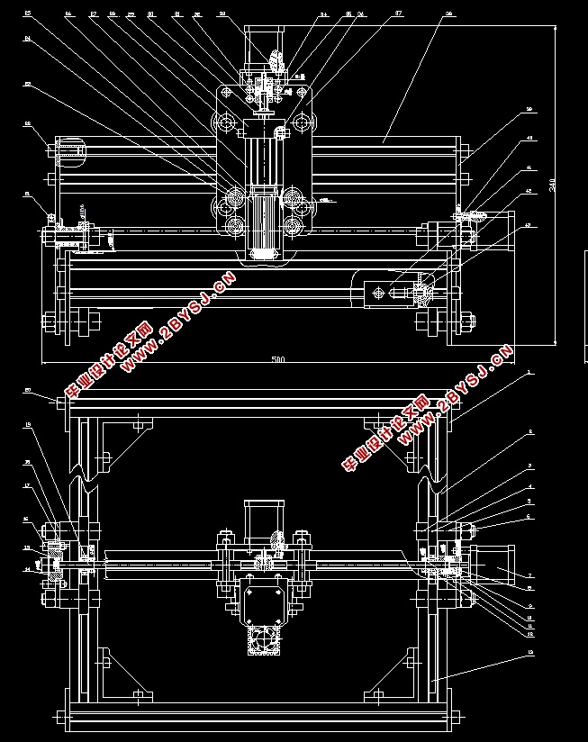
本次设计通过分析激光雕刻机的发展概况和发展现状以及未来发展状况,提出了比较实用的三种激光雕刻机结构方案和方案的比较,并通过理论计算完成激光雕刻机的理论基础。本次设计的激光雕刻机采用了龙门架移动定梁式结构,该结构在X轴和Y轴方向的传动方式采用H型运动方式,通过同步轮与同步带的啮合,同步带保持静止,同步轮与轴承之间距离不变使得同步带在同步轮与轴承之间产生拉紧力,该拉紧力使得各部件之间保持不变的相对关系。通过设计计算对轴和轴承进行校核并校核合格,通过三维装配和虚拟仿真对雕刻机进行真实运动情况的模拟和碰撞检测。因为在材料质量较轻,携带方便,可雕刻大部分不可移动物体,通过固定雕刻机可实现。采用三轴的运动方式使得该激光雕刻机可以雕刻所需要雕刻的三维物体,解决了雕刻机二维雕刻的不足。
关键词:激光;雕刻机;G代码;三维;仿真
Abstrac
Based on the analysis of the general situation of the laser engraving machine, the present situation and the future development situation, the paper puts forward three practical schemes and schemes of the laser engraving machine. The theoretical foundation of laser engraving machine is completed by theoretical calculation. The laser engraving machine designed in this paper adopts the gantry frame moving and fixed beam structure. The transmission mode of the structure in the direction of X axis and Y axis adopts H mode of motion. Through the meshing between the synchronous wheel and the synchronous belt, the synchronous belt remains static. The constant distance between the synchronous wheel and the bearing causes the synchronous belt to produce a tension force between the synchronous wheel and the bearing, which keeps the relative relationship between the components unchanged . The shaft and bearing are checked and checked by design and calculation, and the real motion and collision detection of engraving machine are simulated by 3D assembly and virtual simulation. Because the material is light, easy to carry, can carve most of the immovable objects, can be achieved through a fixed engraving machine. The laser engraving machine can carve three dimensional objects which need to be engraved by using three axis motion mode, which solves the shortage of two dimensional engraving machine.
Keywords:laser;engraving machine;Gcode;3D;Simulation
目 录
摘 要 I
Abstrac II
第1章 绪论 1
1.1 激光雕刻机发展现状及现阶段存在的问题 1
1.1.1 激光雕刻机发展现状 1
1.1.2 激光雕刻机现阶段所存在的问题 1
1.2 激光雕刻未来发展状况及趋势 2
1.2.1 激光雕刻未来发展状况 2
1.2.2 激光雕刻未来发展趋势 2
1.3 本次设计要达到的设计目的 3
第2章 激光雕刻机设计方案及可行性论证 4
2.1 结构方案设计 4
2.1.1 方案一 4
2.1.2 方案二 4
2.1.3 方案三 6
2.2 激光雕刻机设计方案可行性论证 6
2.2.1 方案一评价 6
2.2.2 方案二评价 7
2.2.3 方案三评价 7
2.3 方案确定 7
第3章 机械系统总体设计与计算 9
3.1 整体结构设计 9
3.1.1 结构要求 9
3.1.2 技术参数 9
3.1.3 激光雕刻机坐标系统选择 9
3.1.4 雕刻机的基本结构和自由度分析 9
3.2 雕刻机驱动方案设计 12
3.2.1 典型驱动方案比较 12
3.2.2 雕刻机驱动方案确定 13
3.3 激光雕刻机传动方案设计 13
3.3.1 常见的几种传动机构 13
3.3.2 各部分传动方案设计 16
3.4 电机的选择 18
3.4.1 X方向电机的选择 18
3.4.2 Y方向电机的选择 19
3.4.3 Z方向电机的选择 20
3.5 轴的校核 20
3.6 轴承寿命校核 24
3.6.1 X方向轴承寿命校核 24
3.6.2 Y方向轴承寿命校核 26
3.7 同步带的设计计算 28
3.7.1 X方向同步带的设计计算 28
3.7.2 Y方向同步带的设计计算 30
3.8 丝杠的选型与计算 31
3.8.1选择导轨 31
3.8.2 计算当量载荷 和当量进给转速 32
3.8.3 丝杠螺母副的承载能力校验 32
3.8.4 丝杠螺母副临界转速n的校验 33
3.9 联轴器的选择与计算 34
3.9.1 联轴器的分类 34
3.9.2 联轴器类型的选择 35
3.9.3 X方向联轴器的选用计算 35
3.9.4 Y方向联轴器的选用计算 37
3.10 环境保护和可持续发展方面的思考 38
3.10.1 本次设计对环境影响因素 38
3.10.2 加工前应采取的措施 38
3.10.3 可持续发展方面的思考 38
第4章 产品的使用与维护 39
4.1 产品的使用和注意事项 39
4.1.1 激光雕刻机的使用 39
4.1.2 注意事项 39
4.2 产品维护 39
第5章 毕业设计特色专题 40
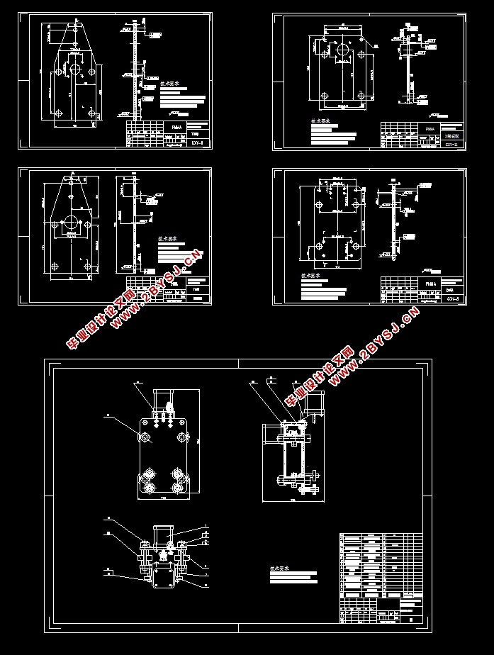
5.1 零件图建模 40
5.1.1 Y轴正板建模 40
5.1.2 Y轴副板建模 41
5.1.3 X轴正板建模 42
5.1.4 X轴副板建模 43
5.2 部件装配 44
5.2.1 X方向部件装配 44
5.2.2 Y方向部件装配 45
5.2.3 Z方向部件装配 46
5.2.4 底座部分装配 46
5.2.5 总装配 48
结 论 49
参考文献 50
致 谢 52