
汽车发动机连杆孔平行度误差检测装置机械结构设计(含CAD零件装配图)
无需注册登录,支付后按照提示操作即可获取该资料.
汽车发动机连杆孔平行度误差检测装置机械结构设计(含CAD零件装配图)(任务书,论文说明书16000字,CAD图纸4张,实习调研报告)
摘 要
连杆是发动机的重要部件。因为连杆的质量直接影响发动机的性能和使用寿命,所以对连杆的尺寸和形位公差有更高的要求。为了确保这些要求,连杆的测试必不可少。
连杆两端孔的要求特别高,则需要很高的平行度,如果连杆孔平行度低则会导致发动机磨损较大,耗油量大,摩擦大,噪音大等一些严重问题。
该装置设计用于测试汽车发动机连杆的两个孔的平行度。该设备的设计原理是在每孔的圆柱面内侧分别测出两个截面上三个不同点的位置,根据三个点 确定一个圆心,两个圆的圆心构成一条直线,在依据数学方法来计算这两条直线的夹角,最后转化成平行度。
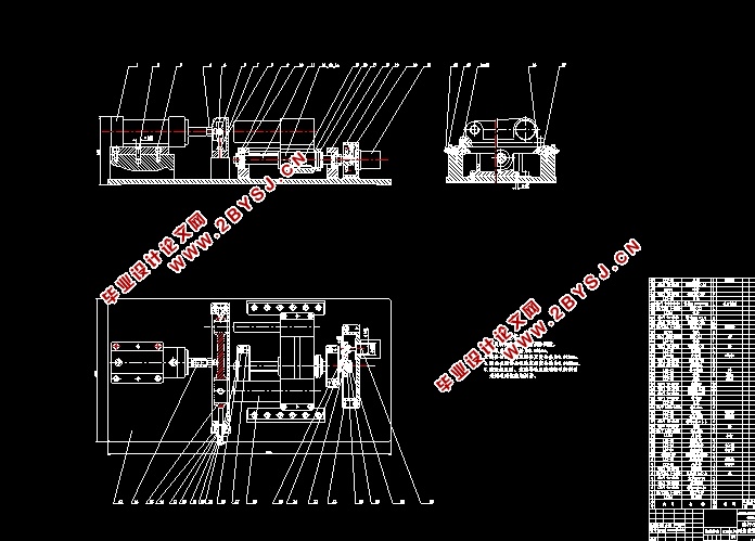
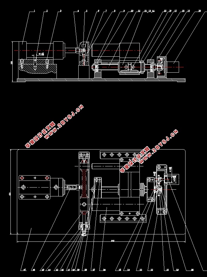
本装置是由机械检测装置和控制部分组成,主要是机械部分的设计,包括齿轮传动的设计及选择,滚珠丝杠的设计及选择,步进电机的选择等。因此设计一套测量连杆大小头孔平行度的检测装置,是保证产品的质量和提高生产效率的重要手段,在加工连杆过程中,对两孔的平行度检验尤为重要,它直接影响连杆的装配精度和使用性能。
关键词: 连杆;平行度;测量
Abstract
Connecting rod is one of key components of engine, whose quality affects engines work performance and life-span directly. Consequently, hing precision of size and form is necessary.The connecting rod is examined in the production to be frequent and to be essential link to ensure hing precision of size and form.
The center line parallelism of the car’s link bar has a high request. If the center line parallelism is not well, the auto engine will have a loud noise, big waste of oil, big friction, fast wear away. So it requests the work-piece have a high center line parallelism.
This testing set is special designed for testing the centre line parallelism of auto engine link bar’s twain aperture. The design principle of this system is: All testing is roboticized, including the data processing before work piece was clamped, the test piece automatic quit after test, testing result display and mimeograph. The characteristic of this set is: The testing precision relatively higher.
In this system, when testing begin, the testing box and the measure pole is dragged by the X direction numerical control table and at the same time, the table was drove by step-electromotor. the fixture adopted hydraulic pressure system, because this system is more placidity and the effect to system’s precision is very small.This set is a whole testing installation. It not only can singly for testing but also for CIMS too.
Key words:connecting rod ; parallelism;examination

目录
摘 要 I
Abstract II
第1章 绪论 1
1.1 设计的概况及研究背景 1
1.1.1 连杆两端孔的要求 1
1.1.2 活塞连杆组装配要点 2
1.2 连杆平行度测量装置的发展趋势 3
第2章 方案设计及可行性论证 4
2.1 连杆平行度检测装置方案设计 4
2.1.1 方案1 4
2.1.2 方案2 4
2.1.3 方案3 5
2.2 连杆平行度检测装置方案可行性论证 6
2.2.1 方案1评价 6
2.2.2 方案2评价 6
2.2.3 方案3评价 7
2.3 方案确定 7
第3章 机械部分的设计选型 8
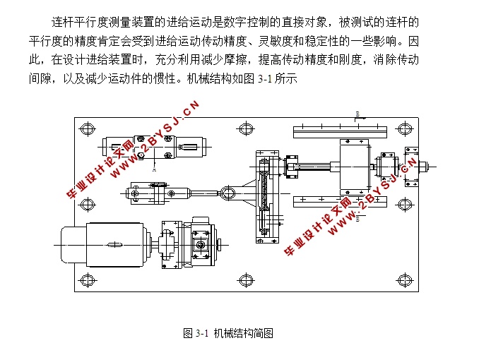
3.1 进给运动的要求 8
3.1.1 减少运动件的摩擦阻力 8
3.1.2 提高传动的精度和刚度 9
3.2 滚珠丝杠的选择 9
3.2.1 滚珠丝杠的安装 9
3.2.2 滚珠丝杠的润滑及防护 10
3.2.3 滚珠丝杠轴向间隙的消除 10
3.2.4 滚珠丝杠的设计计算 11
3.3 齿轮传动的设计计算 14
3.3.1 齿轮的传动比计算 14
3.3.2 确定齿轮模数及有关尺寸 14
3.3.3 转动惯量的计算 15
3.3.4 传动间隙的消除措施 16
3.4 步进电动机的选择 16
3.4.1 电动机的工作原理 17
3.4.2 步进电动机的选择 19
3.5 液压夹具的设计 20
3.5.1 液压夹具的液压基本回路 20
3.5.2 液压元件的选择 21
3.6 传感器的选择及测量原理 22
3.6.1 连杆中心孔平行度误差分析与计算 24
3.7 环境保护和可持续发展方面的思考 25
3.7.1 保护环境 26
3.7.2 坚持可持续发展、积极响应政策进行安全生产 26
第4章 产品使用与维护 27
4.1 连杆的使用 27
4.2 绿色制造 28
第5章 毕业设计特色专题 29
5.1 零件建模 29
5.2 PROE软件简介 30
结 论 31
参考文献 32
致谢 34