EQ6100缸体曲轴孔与凸轮轴孔镗削动力头设计(含液压控制图)
无需注册登录,支付后按照提示操作即可获取该资料.
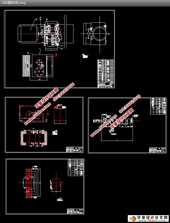
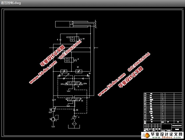
EQ6100缸体曲轴孔与凸轮轴孔镗削动力头设计(含液压控制图)(选题审批表,任务书,开题报告,中期检查表,论文说明书10000字,CAD图5张)
摘 要:主轴及其主轴组件,是组合机床的核心部件,是组合机床进行加工的执行者,在组合机床的发展过程中占有相当重要的地位。一台组合机床的加工精度主要取决于动力头及其主轴组件的精度。现在,很多动力头基本上已经标准化,这为机床的制造,改装带来了很大的方便,但为了提高精度,工作效率,就需要设计出更专用化的动力头部件。
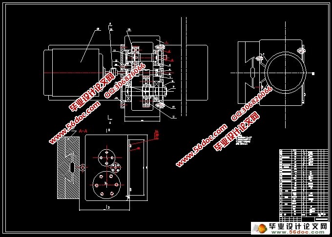
本次设计的镗削动力头主要是用于镗削加工EQ6100缸体曲轴孔与凸轮轴孔。在设计动力头的过程中,主要是依据镗削加工时所需要的切削用量,进行动力源、动力传动、主轴及其组件设计。最后通过校核计算,验算所设计动力头的合理性。
该镗削动力头结构简单,工作可靠,可适用于加工Φ50和Φ104 mm孔,加工精度较高,与通用动力头相比,结构简单、紧凑,可以更好的发挥动力装置的能力,大大提高劳动生产率和加工精度。
通过实际调查,目前,组合机床在工厂中占有很大的比重,需进行镗内孔加工的零件数量也很多,所以,镗削动力头有很大的发展空间和广阔的运用前景。它将会降低机床成本,极大的减轻工人的劳动强度,也更容易实现自动化生产。
关键词:组合机床;动力头;镗削加工
The Design of Boring Machine Kinetie Head for EQ6100 Cam Shaft And Crank Hole
Abstract:The main axle and its the main axle module, is the aggregatemachine-tool core part, is performer which the aggregate machine-toolcarries on the processing, holds the quite important status in theaggregate machine-tool developing process. A aggregate machine-toolprocessing precision mainly is decided by the power head and its themain axle module precision. Now, very many power heads basically already standardize, this for theengine bed manufacture, the reequipment has brought very bigconvenient, but in order to increase the precision, the workingefficiency, needed to design the special-purposer power head part.
The design of Boring is the main driving force for the boring holes EQ6100 cylinder crankshaft and camshaft. In the first design, dynamic process, which is mainly Boring processing required when cutting consumption, power sources, power transmission, Spindle assembly design. Finally, checking, checking dynamic design of the first reasonable .
The first Boring power structure simple and reliable and can be applied to the processing of Φ50-104 mm hole, high precision machining, and General Dynamics compared to the first, simple and compact structure, we can better play the power plant capacity greatly improve labor productivity and accuracy.
Through actual investigations, at present, the combination machine in a factory has a huge proportion require boring hole machining of parts is also a lot of volume, so Boring power head has plenty of room for development and broad application prospects. It will lower the cost of machine, greatly reducing the labor intensity, it would be easier to achieve automated production.
Key words:portfolio machine; dynamic head; boring
零件分析
要求设计一种专用机床的动力头,用于镗削加工EQ6100缸体曲轴孔与凸轮轴孔。材料为HT250,加工要求为:加工精度等级IT7。曲轴孔直径:104mm;凸轮轴直径:50mm;两孔深度:800mm;两孔中心距:130mm
材料为HT250,查《机械设计课程设计手册》 P25页表2-3:HT250的硬度范围为165-2246HBS,在此取180HBS。因为被加工零件加工精度等级IT7,查《机械制造技术基础》 P241页表6-4,根据对零件图的分析比较最后得出加工方案:粗镗—半精镗—精镗。定位基准为:工件的上下底面
6.1 传动装置总传动比
计算传动装置总传动比
i曲=n电/n曲=960/330=2.9
i凸轮轴= n电/n凸轮轴=960/688=1.4
6.2 计算传动装置的运动和动力参数
6.21 转速
根据下面的公式计算各轴转速:
i=n2/n1,T=9550×P/n
则有各轴的转速为
驱动轴I:n1=960r/min
主动轴II:n3=688r/min
主动轴III:n3=330r/min
6.22 功率
驱动轴I: P1=5.5kw
主动轴II:P3=5.456kw
主动轴III:P5=5.456kw
6.23 转矩
驱动轴I:T1=9550P1/n1=54.71N/m
主动轴II:T2=9550P2/n2=75.73N/m
主动轴III:T3=9550P3/n3=157.89N/m


目 录
摘 要 1
关键词 1
1前言 2
2 零件分析 3
3 切削力计算 3
4 电动机的选择 3
5 拟定传动方案 4
5.1 主轴布置方案 4
5.2 主轴布置方案评价 4
6 结构设计 4
6.1 传动装置总传动比 4
6.2 计算传动装置的运动和动力参数 4
6.21 转速 4
6.22 功率 5
6.23 转矩 5
6.3 此轮计算及校核 5
6.31 凸轮轴与驱动轴的齿轮设计与计算及校核 5
6.32 曲轴与驱动轴的齿轮设计与计算及校核 9
6.4 主动轴III的设计、校核 13
6.4.1 初步确定轴的最小直径 13
6.4.2 轴的结构设计 13
6.4.3 求轴上的载荷 14
6.4.4 按弯矩合成应力校核轴的强度 15
6.4.5 精确校核轴的疲劳强度 15
6.5 键的选择及校核 18
6.5.1 键的选择 18
6.5.2 键的校核 18
6.6 轴承 18
6.6.1 轴承的选择 18
6.6.2 轴承寿命的校核 18
7 润滑与密封 21
7.1 润滑 21
7.2 密封 21
8 液压传动 21
8.1 负载分析 21
8.2 负载图和速度图的绘制 22
8.3 液压缸主要参数的确定 22
8.4 液压系统图的拟定 24
8.4.1 液压回路的选择 24
8.4.2 液压原件的选择 25
8.5 油液温升验算 27
9 结论 28
参考文献 28
致谢 28
